dyyseo

Powder surface modification changes the surface state of particles through physical or chemical means, with the core being to break the agglomeration force between particles. When the particle size of the powder decreases to the micrometer or nanometer level, the surface energy sharply increases, and van der Waals forces, hydrogen bonds, and other gravitational forces cause the particles to spontaneously aggregate, forming secondary particles and losing the surface area effect and volume effect of ultrafine powder. Surface modification improves dispersibility from three key dimensions by introducing modifiers: firstly, using coupling agents to construct "molecular bridges" and reduce particle surface energy; The second is to generate spatial hindrance through the coating layer to prevent particle contact; The third is to regulate surface charge, increase electrostatic repulsion, and ultimately achieve uniform dispersion of particles in the medium.


First、 Core mechanism: From molecular action to macroscopic dispersion

1. Reduce surface energy and gravity

The surface of unmodified powders is usually rich in polar groups such as hydroxyl groups, which can easily form hydrogen bonds or electrostatic adsorption between particles. For example, due to the dense hydroxyl groups on the surface, the agglomerate strength of nano zirconia powder can reach several hundred megapascals. By reacting the alkoxy group of silane coupling agent (general formula RnSiX (4-n)) with the hydroxyl group on the surface of the powder, the polar surface can be transformed into a non-polar surface covered with organic groups. The contact angle is increased from hydrophilic 0 ° to hydrophobic 114 ° or more, and the surface energy is reduced by more than 60%. Titanium ester coupling agents anchor the surface of the powder through titanium oxygen bonds, and long carbon chains provide steric hindrance, reducing the dispersed particle size of calcium carbonate in polypropylene from 50 μ m to 2 μ m.


2. Build a spatial obstruction barrier


Physical coating modification forms an elastic shell on the surface of particles through polymer chains, which generates entropy repulsion when particles approach. For example, the MoO3 layer coated with polyacrylic acid can increase the minimum distance between zirconia particles from 5nm to 20nm, effectively preventing agglomeration. Precipitation reaction modification involves the growth of inorganic coatings (such as Al2O3, SiO2) on the surface of particles, and the dispersion is adjusted by controlling the coating thickness (usually 5-50nm). This method increases the coverage power of titanium dioxide in coatings by 30%.

3. Regulating surface charge and Zeta potential


Surfactants form a double layer on the surface of particles by dissociating functional groups, increasing the absolute value of Zeta potential. For example, sodium stearate modified calcium carbonate increased the Zeta potential from 14.1mV to 30.2mV, and electrostatic repulsion improved the stability of the suspension for more than 24 hours. Composite modification (such as aluminum ester+SDS) can synergistically enhance the charge effect and steric hindrance effect, increasing the absolute Zeta potential of silicon carbide powder from 30.5mV to 60mV, and maintaining low viscosity even when the solid content of the slurry reaches 57% (volume fraction).


Second、 Key Technology Paths and Typical Applications

1. Chemical modification: the "molecular bridging" effect of coupling agents

Silane coupling agent: suitable for silicon/hydroxyl containing powders (quartz, kaolin), reacting with resins through functional groups such as amino and epoxy groups. For example, KH-550 treated silicon micro powder can maintain the insulation performance of epoxy sealant at 85 ℃/85% RH environment with a retention rate of>95%.
Titanium ester coupling agent: For calcium carbonate, talc powder, etc., the monoalkoxy type can improve the impact strength of PP composite materials to 45 kJ/m ², while the pyrophosphate type is suitable for powders with a moisture content greater than 0.5%.
Aluminum ester coupling agent: The cost is only 50% of titanium ester, the thermal stability is improved by 20 ℃, and the modified PVC/calcium carbonate system has a notch impact strength of 8kJ/m ².

2. Physical modification: encapsulation and mechanochemistry
Polymer coating: In situ polymerization modification of calcium carbonate with polyvinyl acetate can reduce the melt viscosity of PVC composite materials by 40% and improve processing flowability.
Mechanochemical modification: By high-energy ball milling, the surface lattice of particles is distorted, the active sites are increased, and the reaction efficiency with stearic acid is doubled. The modification time is shortened from 2 hours to 30 minutes.

3. Composite modification: synergistic enhancement strategy
The composite modification of stearic acid titanate (ratio 1:3) was used to treat heavy calcium carbonate, with an activation degree of 99.4% and an oil absorption value reduced to 0.267g/g. The filling amount in PP can reach 30% without reducing the mechanical properties. Salicylic acid and acrylamide are combined to modify silicon carbide, and the isoelectric point is adjusted to pH=12.5 to achieve stable dispersion in alkaline media.


Third、 Effect verification and process optimization

1. Core evaluation indicators


Contact angle and activation index: After modification, the contact angle of the powder is greater than 90 ° (hydrophobic), and an activation index close to 1 indicates complete coating. For example, aluminum ester modified calcium carbonate has a contact angle of 136.3 ° and an activation index of 100%.


Particle size and Zeta potential: The laser particle size analyzer shows a 30% -70% decrease in D50, and a Zeta potential absolute value greater than 30mV is a sign of good dispersion.
Application performance correlation: manifested as a decrease in settling volume in coatings (such as from 4.1mL/g to 1.0mL/g), and an improvement in impact strength in composite materials (such as a 41.97% increase in PP/calcium carbonate system).

2. Key points of the process


Dosage of modifier: 2% -3% for ultrafine powder (particle size<5 μ m) and 0.3% -1.5% for ordinary powder. For example, when using silane coupling agent for nano zinc oxide, a dosage of 2.5% is required to fully cover the surface hydroxyl groups.

Equipment matching: High speed mixers (with a speed of 1000-3000r/min) are suitable for dry modification, while ball mills or sand mills are used for wet modification. The integrated equipment of airflow crushing and modification can increase the discharge rate by 170%.


SAT NANO is a best supplier of nano powder and micro powder in China, we offer oxide powder with surface modification changes if you have any enquiry, please send your enquiry to our email at admin@satnano.com
1.Characterization of particle size and distribution


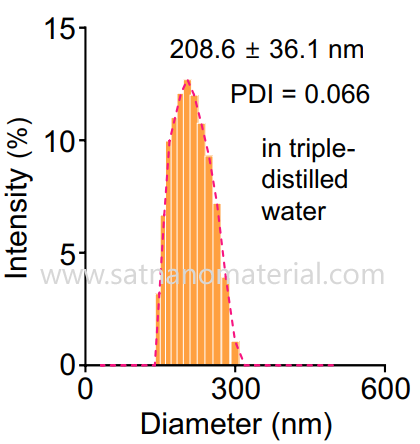
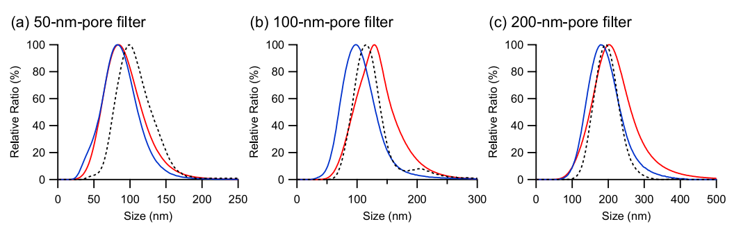
Dynamic Light Scattering (DLS): DLS is one of the most commonly used techniques for measuring the particle size and distribution of nanoparticles in suspensions. It calculates the hydrodynamic diameter of particles by measuring the time-dependent light scattering intensity fluctuations caused by Brownian motion of particles.

DLS can also provide polydispersity index (PDI), which is a dimensionless parameter for evaluating the width of particle size distribution. It is generally believed that a PDI value below 0.3 indicates good dispersion and uniform particle size distribution of the sample; If the PDI value is greater than 0.7, it means that the sample may have severe agglomeration or extremely uneven particle size distribution.

characterize nanoparticle aggregation

Nanoparticle Tracking Analysis (NTA): NTA tracks and records the Brownian motion trajectory of each particle in the field of view in real time through an optical microscope, and then calculates the size of each particle using the Stokes Einstein equation. Compared to DLS, NTA can provide higher resolution particle size distribution information and directly measure particle concentration, which is particularly advantageous for characterizing polydisperse and complex systems.

characterize nanoparticle aggregation

2.Morphological and structural characterization


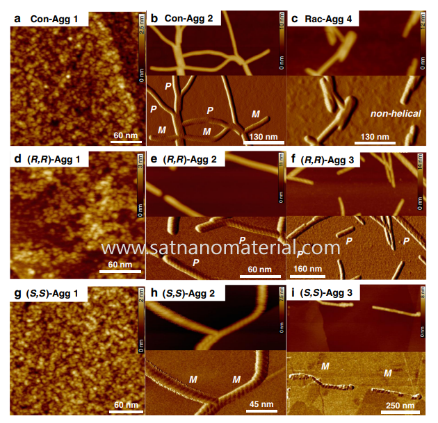
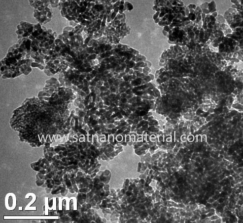
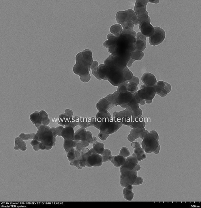
Electron Microscopy (TEM&SEM): Transmission Electron Microscopy (TEM) and Scanning Electron Microscopy (SEM) can provide the most intuitive morphological information of nanoparticles. Through these techniques, researchers can directly observe the size, shape, surface structure, and whether they are in a single dispersed state or forming aggregates of particles. TEM has higher resolution and can even observe the crystal structure of particles. Atomic Force Microscopy (AFM): AFM scans the surface of a sample with a fine probe to obtain three-dimensional morphology images of particles and accurately measure their height and lateral dimensions.

characterize nanoparticle aggregation


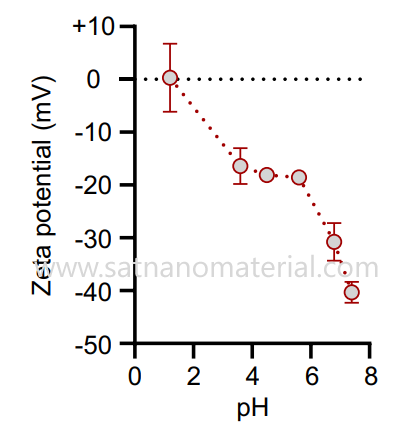
Zeta potential measurement: Zeta potential is a core indicator for evaluating the electrostatic stability of nanoparticles. Calculated by measuring the electrophoretic mobility of particles in an electric field. Generally speaking, there is an empirical relationship between the absolute value of Zeta potential and the stability of the system as follows:
Zeta>60mV: Excellent stability.
Zeta>30mV: Good stability.
Zeta>25mV: The system tends to be unstable and prone to aggregation.
characterize nanoparticle aggregation


SAT NANO is a best supplier of nano powder and micron particle in China, we can offer metal powder, alloy powder, carbide powder, oxide powder, if you have any enquiry, please feel free to contact us at admin@satnano.com


In today's paint and plastic industry, which pursues high performance, lightweight, and environmental protection, traditional fillers and reinforcing agents have long been unable to meet the demands of the high-end market. The emergence of nano high-purity magnesium oxide, with its triple advantages of "filling+reinforcement+functionalization", brings performance leaps to coating and plastic products, becoming a key material to solve the contradiction between material strength, weather resistance, and processability.


Why choose nano high-purity magnesium oxide? Traditional fillers such as calcium carbonate and talcum powder often only have an incremental effect and can even lead to a decrease in material performance, known as the "performance upgrade password" for filling and reinforcement. Nano high-purity magnesium oxide, with a purity of over 99.9% and nanoscale characteristics, has achieved a breakthrough of "filling without degradation, reinforcement more efficiently".

nano high-purity magnesium oxide

Comprehensive improvement in mechanical performance

Nanoparticles can be uniformly dispersed in the matrix, significantly improving the mechanical properties of materials through interface strengthening effects. Adding 5% -8% nano high-purity magnesium oxide to plastic products can increase tensile strength by 25% -40% and impact toughness by more than 30%, solving the problem of material brittleness caused by traditional fillers. In the coating system, it can form a three-dimensional network structure, improving the adhesion of the coating to level 0 and increasing wear resistance by 50%, making it easy to cope with high-frequency friction scenarios.

Double the ability to withstand weather and corrosion

Its excellent chemical stability endows the material with super strong weather resistance. After adding nano high-purity magnesium oxide to outdoor coatings, the UV aging resistance time is extended to over 3000 hours, and the color difference change Δ E is less than 1.5; In plastic products, the temperature resistance range can be expanded to -60 ℃ -180 ℃, and the service life in humid and hot environments can be extended by 2-3 times, perfectly adapting to harsh scenarios such as automotive exterior and outdoor building materials.


Optimization and upgrade of processing performance

Compared with traditional fillers, nano high-purity magnesium oxide has an extremely low oil absorption value (<20g/100g), which can reduce the amount of additives used in coatings and plastic processing, and lower the viscosity of the system. In plastic extrusion molding, the melt flowability is improved by 15% -20%, and the production efficiency is increased by 20%; In coating preparation, the grinding time can be reduced by 30%, and the storage stability is significantly enhanced, with a settling rate of less than 1% per month.

From laboratory to production line: the 'performance revolution' of multi scenario applications

Nano high-purity magnesium oxide, with its multifunctional properties, has been widely applied in various sub fields of coatings and plastics, becoming a "performance standard" for high-end products

Coatings field: Creating high-performance protective coatings

In industrial anti-corrosion coatings, nano high-purity magnesium oxide works synergistically with anti-corrosion pigments to form a dense passivation film, increasing the salt spray testing time from 500 hours to over 1500 hours. It can be used in heavy-duty anti-corrosion scenarios such as marine engineering and chemical equipment. In building exterior wall coatings, it can endow the coating with self-cleaning function, with a residual stain rate of less than 5% after rainwater erosion, and a 40% increase in stain resistance, keeping the exterior wall clean and beautiful for a long time. In automotive coatings, the addition of nano high-purity magnesium oxide to the topcoat can achieve a glossiness of over 95%, improve clarity by 20%, and significantly enhance stone impact resistance, reducing paint damage.


Plastic field: Empowering high-end product upgrades

In engineering plastics, nano high-purity magnesium oxide can replace some glass fibers for the preparation of automotive engine peripheral components, achieving a weight reduction of 10% -15% while ensuring strength, and raising the heat-resistant deformation temperature to above 180 ℃. In the plastic of wires and cables, the volume resistivity increases by 1-2 orders of magnitude after addition, the flame retardant level reaches UL94 V-0 level, and the weather resistance is improved, which can meet the long-term use needs of outdoor cables.

Originating from three core technological breakthroughs: precise control of surface modification

By surface modification with coupling agents such as silane and titanate, the compatibility between nanoparticles and organic matrix is improved by more than 60%, solving the industry problem of easy aggregation of nanomaterials and ensuring uniform and stable performance.

Accurate control of particle size distribution

By adopting advanced hydrothermal synthesis technology, the particle size can be precisely controlled within the range of 10-50nm. The particle size distribution can be customized according to the needs of different coating and plastic systems, maximizing the nano effect.

In the increasingly competitive paint and plastic industry, material performance has become the core competitiveness of product differentiation. Nano high-purity magnesium oxide not only reduces raw material costs (replacing some expensive resins or functional additives), but also endows products with high added value, helping enterprises seize market share in the high-end market.
From industrial anti-corrosion to automobile manufacturing, from building decoration to medical devices, nano high-purity magnesium oxide is reshaping the performance boundaries of coating and plastic materials with the advantage of "small addition, big change". Now, join this material upgrade revolution and make your products comprehensively leading in performance, environmental protection, and cost!

SAT NANO is a best supply of MgO nanopowder in China, we can offer 50nm, 100nm and 1-3um, if you have any enquiry, please feel free to contact us at admin@satnano.com

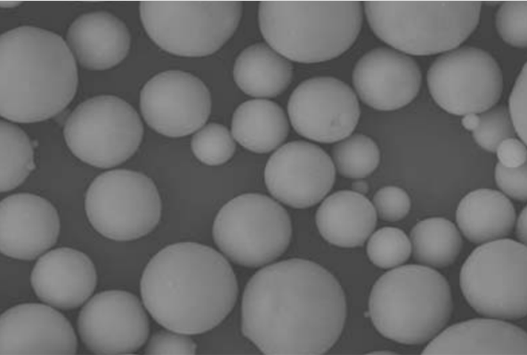
With the increasing demand for high thermal conductivity materials, filled thermal conductive polymer composites have good application prospects. The performance of thermal conductive composite materials largely depends on the selection of thermal conductive fillers. Aluminum oxide (Al2O3)is a common ceramic filler with high hardness and good thermal conductivity, and is a commonly used choice to improve the thermal conductivity of materials.

Aluminum oxide


1.Unique Advantage: The spherical structure endows a unique advantage


Excellent thermal conductivity. Aluminum oxide is an inorganic non-metallic material with excellent thermal conductivity, and its spherical structure further optimizes its thermal conductivity path. In composite materials, spherical particles can form a more continuous and smooth thermal conductivity network, thereby reducing thermal resistance. When heat is transferred inside the material, the contact area between spherical particles is relatively large and distributed more evenly, avoiding heat transfer interruptions caused by irregular shapes, large edges, or stacking gaps, thereby significantly improving the overall thermal conductivity of the composite material.

Excellent dispersibility. The spherical structure endows alumina powder with good fluidity and dispersibility. Compared with irregularly shaped alumina powders such as flake, needle, and block powders, spherical particles have less friction between each other and are more easily evenly distributed in the matrix material, thereby reducing the occurrence of aggregation. This uniform distribution ensures the continuity and consistency of the thermal conductivity network in composite materials, avoiding thermal conductivity fluctuations caused by local particle aggregation.

Good chemical stability and high temperature tolerance. Spherical alumina fillers have strong chemical stability and are not prone to chemical reactions with surrounding media. In acidic and alkaline environments, humid environments, or long-term use, its physical and chemical properties remain stable and will not degrade due to corrosion, oxidation, or other factors, ensuring the long-term reliability of thermal conductive materials. At the same time, it has excellent high-temperature resistance and can maintain structural integrity and thermal conductivity in high-temperature environments.


2. Preparation process: precise shaping from "powder" to "sphere"


The excellent performance of spherical alumina lies in its precise spherical structure and controllable particle size distribution, which cannot be separated from mature preparation processes. At present, the preparation methods of spherical alumina powder mainly include: flame melting method, jet method, template method, aerosol decomposition method, sol gel method, hydrothermal method, dropping ball method and ball milling method.


(1) Spray method
The preparation of spherical alumina by spray method uses a high-temperature heat source to heat treat the precursor, and then utilizes surface tension to spheroidize the product. The spray method is divided into spray pyrolysis method, spray drying method and spray melting method. The jet melting method uses radio frequency induced plasma to treat solid alumina into a molten state, and then uses jet high-speed cooling to obtain spherical alumina. This method mainly performs spheroidization treatment on irregularly shaped alumina particles. After treatment, the alumina has high sphericity, but it is difficult to control the particle size scale, which ranges from nanometer to micrometer.

(2) Flame melting method
Currently, flame melting method is commonly used in the market to prepare spherical alumina. Compared with the "jet melting method" with a similar name, the flame melting method directly sprays irregularly shaped alumina powder into the flame, causing the alumina powder to melt into balls in the flame. The process is simple and has more advantages in cost control than the plasma flame spraying method. The products produced by balling have high thermal conductivity, good sphericity, and controllable particle size

(3) Template method
The preparation of spherical alumina by template method first requires a core template, which is wrapped with a layer of shell structured microspheres outside the core template. Then, the core template is removed by physical and chemical methods, and finally hollow microspheres are obtained. According to the characteristics and limitations of the template itself, it is generally divided into hard template method and soft template method

(4) Aerosol decomposition method
The preparation of alumina spheres by aerosol decomposition method mainly uses liquid aluminum alkoxide as raw material. The aluminum alkoxide is first gasified by high-temperature hydrolysis, and then dried or treated at high temperature to form spherical alumina powder. The particle size prepared by this method is in the nanometer range and has not yet been industrialized.

(5) Sol gel method
The sol gel method is to obtain aluminum oxide powder through alcohol washing, aging and heat treatment from the precursor formed by inorganic salt water hydrolysis or polymerization. Due to the use of organic solvents and surfactants in this method, the sphericity of the obtained alumina powder is close to 100%, and the particle size is in the micrometer or millimeter range. The disadvantage of this method is that it is not conducive to the separation and drying of alumina powder.

(6) Hydrothermal method
The hydrothermal method for preparing spherical alumina is to use aluminum salts as raw materials, dissolve and recrystallize the substances in a high-temperature and high-pressure reaction environment, and grow them into spherical alumina particles. The alumina powder produced by hydrothermal method has high purity, controllable shape, and no agglomeration, but requires high temperature and high pressure environment, which is highly dependent on equipment.


(7) Drip ball method
The first step in preparing spherical alumina by droplet method is to prepare pure alumina sol. Starting from acidic alumina sol, the alumina sol is dropped into the oil layer, and the gelling agent is HMTA (hexamethylenetetramine) or a mixture of urea and HMTA. After aging, drying, and calcination, spherical alumina is formed. The droplet method is mainly used to prepare spherical alumina with a particle size of millimeter or larger. During the operation, hot oil is required and the sol must be kept dripping for a long time.


(8) Ball milling method
The ball milling method is to put the raw materials into a ball mill, grind and stir them with a grinding agent, and extract large particles into ultrafine powder. Mechanical ball milling can be used to prepare spherical alumina products with different particle sizes. This method has simple and reliable equipment, is easy to mass produce, and has great development prospects in the future market.

As a core material in the field of thermal conductive fillers, spherical alumina plays an irreplaceable role in the development of high-end industries due to its unique structural advantages, excellent performance, and wide application scenarios.


SAT NANO is a best supplier of spherical alumina powder in China, we can offer nano particle and micro particle, if you have any enquiry, please feel free to contact us at admin@satnano.com

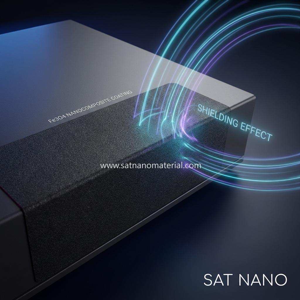
This guide provides a comprehensive technical framework for utilizing magnetite (Fe3O4) nanopowder as a functional filler to formulate industrial protective coatings with superior antistatic and electromagnetic shielding properties. It specifically addresses critical engineering challenges such as nanoparticle agglomeration, sedimentation, percolation threshold optimization, and coating adhesion.

fe3o4 nanopowder coating


1. Fundamental Principles & Formulation Logic

1.1 Dual Conductive and Magnetic Mechanisms

  • Electrostatic Discharge (ESD) / Antistatic: Magnetite (Fe3O4) is a semiconductor with a room-temperature resistivity of approximately 10−2102 to 10−3 Ω⋅cm103 Ωcm. Once uniformly dispersed in a polymer matrix at a sufficient concentration, the nanoparticles contact each other (or utilize the tunneling effect) to establish a continuous conductive network, allowing static charges to bleed off safely.
  • Electromagnetic Interference (EMI) Shielding: Unlike purely carbonaceous or metallic conductive coatings, Fe3O4 is ferrimagnetic. When electromagnetic waves impinge on the coating, it attenuates the magnetic component through hysteresis loss, domain wall resonance, and eddy current losses, absorbing electromagnetic radiation.


1.2 Single-Filler Limitations and Synergistic Networks


Due to the moderate intrinsic resistivity of Fe3O4 compared to pure metals (Ag, Cu, Ni), relying solely on Fe3O4 to achieve a high shielding rating (surface resistivity <104 Ω/sq) requires high loading levels (typically 30%∼50%30%50% by weight). This severe loading dramatically increases coating viscosity, compromises mechanical properties (brittleness), and severely weakens substrate adhesion.

  • Recommended Solution: A "Fe₃O₄ / Carbonaceous Filler" Synergistic Conductive Network. Introducing a minor fraction (0.5%∼1.5%0.5%1.5% by weight) of Multi-Walled Carbon Nanotubes (MWCNTs) or conductive carbon black allows them to act as "conductive bridges" connecting the Fe3O4 nanoparticles. This dramatically lowers the percolation threshold, multiplies electrical conductivity, and reduces the necessary Fe3O4 loading to a manageable 15%∼25%15%25%.


2. Typical Solvent-Borne 2K Epoxy Formulation

Ingredient
Recommended Specification
Weight Parts (pbw)
Function / Mechanism
Film-Forming Binder
Epoxy Resin E-51 (DGEBA)
100
Primary binder; provides excellent corrosion resistance and mechanical adhesion
Reactive Diluent
Butyl Glycidyl Ether (BGE)
10 ~ 15 Reduces initial resin viscosity for easier filler incorporation
Primary Functional Filler
Modified Fe3O4 Nanopowder (20 ~ 50 nm)
25 ~ 35
Conductive and magnetic absorber core
Co-Filler (Optional)
Multi-Walled Carbon Nanotubes (MWCNTs)
0.5 ~ 1.5
Bridges nanoparticles to establish a robust conductive network
Wetting & Dispersing Agent
High-molecular-weight block copolymer (e.g., BYK-110)
1.0 ~ 2.0
Steric stabilization; lowers viscosity and prevents agglomeration
Anti-Settling Agent
Fumed Silica (e.g., Aerosil 200 or modified)
0.8 ~ 1.5
Builds a thixotropic network to prevent heavy iron settling
Leveling & Defoaming Agents
Polyether-modified silicone
0.3 ~ 0.5
Eliminates air bubbles and micro-pinholes, ensuring a smooth finish
Solvent Blend
Xylene : Butanone : Butyl Acetate = 4:3:3
~30 ~ 50
Adjusts viscosity to standard application parameters (20-30s, Ford Cup #4)
Curing Agent (Part B)
Polyamide Curing Agent (e.g., Polyamide 650)
50 ~ 60
Crosslinks with Part A at room or elevated temperature


3. Step-by-Step Preparation Process

Nanoparticles possess extremely high surface energy and naturally form tight secondary agglomerates. Standard low-shear mixing is insufficient to break these structures. The following four-stage protocol must be followed:

Stage 1: Surface Chemical Modification (Wet Silanization)

This stage replaces hydrophilic surface hydroxyls with organophilic chains, preventing re-agglomeration and enhancing compatibility with organic resins.

  1. Prepare Hydrolysis Solution: Mix anhydrous ethanol and deionized water (95:5 wt. ratio). Add Silane Coupling Agent KH-550 (equivalent to 1.5%∼2.0%1.5%2.0% of the weight of Fe3O4). Adjust the pH to 4.0 ~ 5.0 using glacial acetic acid. Stir at room temperature for 30 minutes to ensure full hydrolysis of the silane.
  2. Ultrasonic Dispersion: Disperse the Fe3O4 nanopowder in the silane solution. Subject the suspension to high-intensity ultrasonic treatment for 30 ~ 45 minutes to disrupt loose physical clusters.
  3. Reflux Reaction: Transfer the suspension to a three-necked flask equipped with a mechanical stirrer and a reflux condenser. Heat to 75 ~ 80 °C under vigorous stirring for 3 hours.
  4. Washing & Collection: Cool the mixture. Position a strong neodymium-iron-boron (NdFeB) magnet under the flask to magnetically separate the Fe3O4 nanoparticles. Decant the supernatant, replenish with anhydrous ethanol, and repeat the washing cycle 3 times to remove any unreacted silane.
  5. Drying & Pulverization: Dry the wet paste in a vacuum oven at 70 °C for 12 hours. Gently mill the dried cake back into a fine, organophilic Fe3O4 powder.


Stage 2: Pre-Mixing


  1. Charge the epoxy resin, reactive diluent, solvents, and the wetting/dispersing agent (BYK-110) into a mixing vessel.
  2. Set the high-speed dissolver to 500 rpm. Gradually charge the modified Fe3O4 nanopowder and the carbon co-fillers.
  3. Increase the shear speed to 1500 ~ 2000 rpm and disperse for 30 ~ 45 minutes to wet the fillers thoroughly.


Stage 3: High-Energy Bead Milling (Critical Step)


  1. Bead Milling: Pump the pre-mixed slurry into a horizontal bead mill charged with 0.2 ~ 0.4 mm yttria-stabilized zirconia beads (70~80% filling ratio).
  2. Temperature Control: Run the slurry through 3 ~ 4 passes. Keep the mill's cooling jacket active, maintaining the product temperature below 50 °C to prevent premature resin polymerization.
  3. Fineness Verification: Check the fineness using a hegman gauge. Stop milling once the reading is ≤10 μm10 μm and the paste possesses a glossy, buttery texture.


Stage 4: Post-Addition & Stabilization


  1. Blend in the leveling agent, defoamer, and the pre-dispersed fumed silica paste at 800 rpm.
  2. Filter the coating base through a 200-mesh (75 μmμm) screen to eliminate any stray particles. Package and seal as Part A (Base).


4. Coating Application Guide


4.1 Substrate Treatment

Adhesion dictates the longevity and reliability of the shielding layer.

  • Metal substrates (Steel, Aluminum enclosures): Solvent degrease, then grit-blast (Sa 2.5) or abrade to profile the surface.
  • Plastic substrates (ABS, PC): Clean with isopropyl alcohol to remove mold release agents. Consider plasma treatment or a light plastic primer to promote chemical bonding.

4.2 Mixing and Induction

  • Blend Part A (Base) and Part B (Curing Agent 650) at a 100 : 50 weight ratio (or as specified by the curing agent's amine value).
  • Adjust viscosity by adding the solvent blend under mechanical agitation.
  • Induction (Aging) Time: Let the mixture stand for 15 ~ 20 minutes before spraying. This initiates pre-polymerization and helps expel microbubbles.
  • Pot Life: Use the catalyzed paint within 4 hours; discard if gelation begins.

4.3 Spraying Process

  • Pneumatic Air Spraying is highly recommended to achieve a uniform, isotropic network. Use a nozzle size of 1.2 ~ 1.5 mm and air pressure of 0.3 ~ 0.5 MPa.
  • Apply in multiple wet-on-wet passes (15∼20 μm1520 μm per pass) with a 10-minute flash-off time between passes. Aim for a total dry film thickness (DFT) of 35 ~ 50 μmμm.


4.4 Curing Conditions

  • Ambient Cure: Dry-to-touch in 2 hours, hard-dry in 24 hours (full chemical cure in 7 days at 25 °C).
  • Forced Cure (Recommended): Allow a 30-minute flash-off, then bake in an oven at 80 °C for 2 hours. Thermal curing induces matrix shrinkage, compressing the conductive fillers closer together to yield a superior conductive/shielding performance.


5. Performance Evaluation & Technical Metrics


  1. Surface Resistivity:
    Measure via a 4-point probe or high-resistance meter.
    • Antistatic Threshold: Surface resistivity should fall between 105∼109 Ω/sq105109 Ω/sq.
    • Electrostatic/EMI Shielding Grade: Surface resistivity <104 Ω/sq<104 Ω/sq (achievable with the Fe3O4Fe3O4/MWCNT co-filler formulation).
  2. Cross-Cut Adhesion:
    Per GB/T 9286 or ASTM D3359, the coating must achieve a rating of Class 0 or 1 (no peeling).
  3. EMI Shielding Effectiveness (SE):
    Evaluate in the 30 MHz ~ 1.5 GHz band using a coaxial flange test fixture (ASTM D4935) to measure attenuation in decibels (dB).


6. Engineering Pitfalls & Best Practices


  1. The Settling Catastrophe:
    The density of Fe3O4 (5.18 g/cm35.18 g/cm3) is far higher than that of epoxy resin (approx. 1.2 g/cm31.2 g/cm3). Unstabilized nanoparticles settle into an extremely hard sediment that cannot be re-dispersed.
    • Mitigation: Never omit the fumed silica or polyamide wax (thixotropic agent). This creates a strong yield stress under static conditions to lock the nanoparticles in place, while thinning immediately under shear.
  2. Thermal Oxidation Risk:
    Nanoparticles have extremely high chemical activity. If the temperature spikes during milling or drying, magnetite can oxidize into hematite (α-Fe2O3α-Fe2O3), which is non-magnetic and poorly conductive (destroying the shielding properties). Always maintain the water-cooling jacket during milling.
  3. Stoichiometric Precision:
    Always weigh the curing agent precisely. Epoxies do not dry by evaporation; they cure via stoichiometry. An incorrect ratio leads to sticky film or brittle, highly stressed coatings that crack and break the shielding pathways.


Technical Solution: Nickel Ferrite (NiFe2O4) for Advanced EM Absorption & Shielding


1. Material Identification

Nickel Ferrite (NiFe2O4) is a high-performance soft magnetic ferrite with an inverse spinel structure. In this configuration, Ni2+Ni2+ ions and half of the Fe3+Fe3+ ions occupy octahedral sites, while the remaining Fe3+Fe3+ ions occupy tetrahedral sites.

  • Physical Form: Ultra-fine black or dark gray nanopowder.
  • Key Characteristics:
    • High Curie Temperature (≈585∘C≈585∘C): Maintains magnetic stability in high-temperature environments.
    • High Electrical Resistivity: Unlike metallic powders, it minimizes eddy current losses at high frequencies.
    • Chemical Stability: Highly resistant to oxidation, corrosion, and environmental degradation.

Nife2O4


2. Functional Roles & Mechanisms

In the design of Electromagnetic (EM) functional materials, Nickel Ferrite serves two critical roles:


2.1 Magnetic Loss Mechanism

It attenuates EM energy primarily through magnetic hysteresis loss, domain wall resonance, and natural resonance. It is particularly effective in the 1 MHz to 18 GHz range, converting magnetic field energy into heat.


2.2 Impedance Matching Optimizer

A major challenge with high-conductivity fillers (like Carbon Nanotubes) is that they reflect waves at the surface. Nickel Ferrite has a relatively high magnetic permeability (μμ) and a moderate dielectric constant (εε). This balance helps the material achieve impedance matching (Zin≈Z0Zin≈Z0), allowing EM waves to enter the coating rather than reflecting off the surface.


2.3 High-Frequency Performance

Due to its high resistivity, NiFe2O4NiFe2O4 can operate at much higher frequencies than traditional iron powders without suffering from the "Snoek's Limit" bottleneck as severely.

Absorption AND Shielding


3. Technical Parameters (Typical 2-18 GHz Range)

The following values represent typical performance metrics for NiFe2O4NiFe2O4 dispersed in a polymer matrix (at 30-40% loading):


Parameter
Symbol
Typical Value Range
Real Permittivity
ε′
4.0 ~ 9.0
Imaginary Permittivity
ε′′
0.01 ~ 1.0 (Low dielectric loss)
Real Permeability
μ′
1.1 ~ 2.0
Imaginary Permeability
μ′′
0.1 ~ 0.8 (Moderate magnetic loss)
Magnetic Loss Tangent
tanδμ

0.1 ~ 0.5
Reflection Loss (RL)
RLmin

−20 dB to −45 dB−45 dB (99% to 99.99% absorption)
Effective Bandwidth
EAB
4.0 ~ 6.5 GHz (where RL < -10 dB)
Shielding Effectiveness
SE
5 ~ 15 dB (Pure); 30 ~ 70 dB (Composite)


4. Integrated Application Solution

To overcome the density of pure ferrite and its relatively low dielectric loss, we recommend a "Magneto-Dielectric Synergistic System."


4.1 Recommended Formulation Concept


4.2 Preparation Workflow

  1. Surface Modification: Treat NiFe2O4NiFe2O4 with a silane coupling agent to enhance organophilic properties.
  2. High-Energy Dispersing: Use ball milling or bead milling to create a homogeneous mixture of the ferrite and carbon co-fillers in the resin.
  3. Application: Spray or cast to a calculated matching thickness (typically 1.5∼2.5 mm for X-band or Ku-band targets).


5. Strategic Conclusion

Nickel Ferrite (NiFe2O4) is a "versatile" filler for modern EM protection.


1. Intrinsic Color: Black

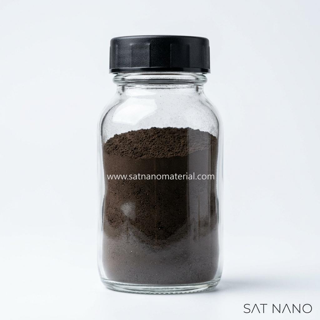
Bulk (micron-scale) pure Fe3O4(Magnetite) appears deep black under visible light.

  • Reason: Fe3O4 is a narrow-bandgap semiconductor (bandgap ≈0.1≈0.1 eV), which absorbs light across the entire visible spectrum with virtually no reflection, resulting in a pure black appearance.
  • Industrial products: Larger-particle Fe3O4powders (micron-scale or highly crystalline nanoparticles), if kept free of surface oxidation, retain the standard black color.


2. The Nanoscale Color Shift: Reddish-Brown / Russet

When Fe3O4 particle size is reduced to the nanoscale (typically < 30 nm), the color often shifts from pure black toward reddish-brown or russet. This is driven by two synergistic factors:


A. Surface Oxidation (Primary Cause)

Nanoparticles possess an extremely high specific surface area, with surface atoms accounting for a vastly greater proportion than in micron-scale particles. Fe3O4 nanoparticles readily undergo surface oxidation when exposed to air, water, or during synthesis:

4 Fe3O4+O2⟶6 γ-Fe2O34 +O2⟶6 γ-Fe2O3

  • Result: A "Core-Shell" Structure forms:
    • Core: Retains black Fe3O4(magnetite).
    • Shell: Oxidized into brown-colored γ-Fe2O3 (maghemite).
  • When the particle size is extremely small (e.g., 10-15 nm), the shell-to-core volume ratio becomes significant, and the overall color shifts from black toward reddish-brown.
  • The smaller the particle, the larger the specific surface area, the higher the degree of oxidation, and the more pronounced the red/brown hue.


B. Quantum Size Effects & Light Scattering

  • Absorption Band Blue-Shift: Due to quantum confinement effects, the absorption spectrum of nano-Fe3O4Fe3O4 undergoes a blue-shift relative to the bulk material. The originally full visible-light absorption is weakened, allowing selective scattering or reflection of shorter wavelengths.
  • Rayleigh Scattering: When particle dimensions are far smaller than visible wavelengths (380-780 nm), Rayleigh scattering dominates. Scattering intensity is inversely proportional to the sixth power of particle size, meaning shorter wavelengths (blue-violet) are scattered more strongly, shifting the reflected light toward warm tones (red/brown).


3. Color vs. Particle Size / Purity Summary

Appearance

Corresponding State
Probable Cause
Pure Black
Large particles (> 100 nm) or strict oxygen-free protection
Intact lattice, no surface oxidation, full-spectrum absorption
Dark Brown-Black
Medium particles (30-50 nm), minor air exposure
Surface oxidation begins; thin γ-Fe2O3 shell forms
Reddish-Brown
Ultra-fine particles (< 20 nm), stored in air
Significant oxidation; shell thickness comparable to core; color dominated by γ-Fe2O3

Bright Red
Fully oxidized or high-temperature calcined
Completely converted to α-Fe2O3 (Hematite); no longer Fe3O4


4. Practical Engineering Recommendations


The development of conductive pastes began in the 1950s. In 1954, British scholar C.F. Powell first reported the method of preparing conductive pastes by suspending silver particles in organic solvents, laying the technical foundation. Subsequently, in the 1960s and 1970s, with the rise of thick film hybrid integrated circuits, precious metal conductive pastes such as silver paste and gold paste gradually achieved initial industrialization and were mainly used in the aerospace and military industries; Taking photovoltaic silver paste raw materials as an example, silver powder accounts for over 90% of the cost, and the purchase price of silver powder is greatly affected by market silver prices, with significant fluctuations Since 2020, driven by high silver prices and the demand for cost reduction, silver coated copper paste has been introduced and applied in HJT battery production lines. Breakthroughs have been made in pure copper paste and electroplated copper technology, and mass production has been launched. The silver content has been significantly reduced, and the silver free process has significantly accelerated.


At present, the three mainstream technological directions for replacing conductive silver paste are: silver coated copper paste, electroplated copper process, and pure copper/aluminum paste. They aim to solve the problem of high silver prices and have entered the industrialization stage in fields such as photovoltaics and LED packaging.

The core differences between these three technological routes are as follows:
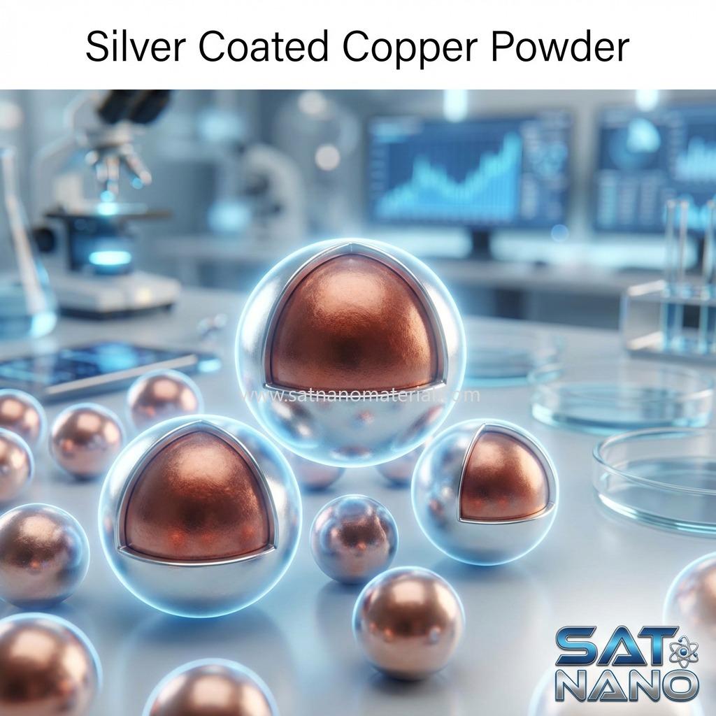
1. Silver in Copper Technology Silver in Copper is currently the most mature and rapidly industrializing copper replacement solution. Its core is the core-shell structure of copper core and silver shell, partially replacing silver with copper. By adjusting the doping ratio of silver and copper, the slurry cost can be effectively reduced while ensuring the photoelectric conversion efficiency, and the cost reduction can reach more than 30%. However, due to the easy oxidation of copper powder in high temperature environments, the application of this scheme has obvious limitations and is only suitable for low-temperature silver paste systems in crystalline silicon heterojunction (HJT) photovoltaic cells and stacked photovoltaic cells.

silver coated copper powder


The emergence of silver coated copper powder is mainly aimed at significantly reducing costs while maintaining conductivity close to pure silver. SAT NANO technician Dana obtained the following comparative data based on experiments with conductive silver powder and conductive silver coated copper powder.

 Here is a comparison of the key performance parameters between the two:

Technical Parameter
Conductive Silver Powder (Pure Ag)
Conductive Silver-coated Copper Powder (Ag-coated Cu)
Comparison Summary
Volume Resistivity
10−5∼10−4 Ω⋅cm
10−4∼10−3 Ω⋅cm
Silver is slightly superior, but Ag-coated Cu meets most industrial requirements.
Stability / Reliability
Excellent; highly resistant to oxidation.
High; depends on the density and integrity of the silver coating.
Pure silver offers superior long-term electrical stability.
Density
Approx. 10.5 g/cm310.5 g/cm3
Approx. 8.9∼9.1 g/cm38.9∼9.1 g/cm3
Ag-coated Cu is lighter, providing a higher filling volume per unit mass.
Silver Content (Ag %)
99.9%∼100%
3%∼30% (Commonly 10%∼20%)
Ag-coated Cu significantly reduces the consumption of precious metals.
Cost / Price
High (Highly sensitive to silver market fluctuations).
Approx. 1/3∼1/51/3∼1/5 of Pure Silver Powder.
Ag-coated Cu has a definitive cost advantage.


2. Copper electroplating technology is based on the principle of electrolytic deposition, which can utilize the transparent conductive layer and edge guide structure pre-set on both sides of the photovoltaic cell to synchronously prepare metal electrodes on the front and back of the cell, without the need for high-temperature sintering and single-sided step-by-step processing. It has natural double-sided metal compatibility and can fully utilize the performance advantages of HJT battery double-sided power generation; At the same time, copper plated electrodes have significantly better conductivity and contact characteristics with transparent conductive oxide (TCO) layers than traditional silver grid lines. They are made of pure copper material and have a dense structure without voids, with a much lower electrical resistivity than low-temperature silver paste. This can effectively reduce electrode ohmic losses and series resistance, and are tightly combined with TCO transparent conductive films without contact holes, which can reduce contact resistance, improve electrode adhesion and carrier transport collection efficiency; In addition, copper plated electrodes can achieve ultrafine line widths of 15-20 μ m, with better aspect ratios and good plasticity. Compared with silver grid lines printed with 30-40 μ m, they can significantly reduce shading losses. Combined with low resistivity characteristics, they can effectively improve the generation and collection efficiency of photo generated carriers, and increase the conversion efficiency of heterojunction photovoltaic cells by 0.3% to 0.5%. At present, the copper electroplating process still faces certain difficulties in mass production. Compared with traditional screen printing, the electroplating copper process has a longer process and is prone to situations such as grid detachment and oxidation. Moreover, due to the complex process flow, the initial equipment investment cost is relatively high. On the other hand, the electroplating solution contains a large amount of harmful chemicals, which poses environmental compliance risks and to some extent restricts its large-scale promotion. Currently, the industrialization of copper electroplating technology still needs time.


3. Pure copper paste is the most ideal silver free cost reduction solution in the medium to long term, which can completely replace silver paste and has the greatest potential for cost reduction. However, its large-scale application still faces core technical challenges. Due to the active chemical properties and high specific surface energy of copper powder, it is prone to contact with air during preparation and battery production to form insulating oxide films, resulting in a decrease in the conductivity of the slurry. Therefore, the technological breakthrough in antioxidant treatment of copper powder has become the key to the industrial application of copper slurry. At present, pure copper paste products for low-temperature and high-temperature routes are still in the research and development testing stage.

silver coated copper powder


SAT NANO is a best supplier of silver powder, silver coated copper powder in China, we can supply different partcile size, if you have any enquiry, please feel free to contact us at admin@satnano.com

In transmission electron microscopy (TEM) analysis, the primary and crucial step in obtaining a high-quality image that can be interpreted reasonably is sample preparation. Inappropriate sample thickness, poor conductivity, or damage introduced during sample preparation can directly lead to abnormal electron beam penetration, image distortion, and even sample scrapping.

TEM sample requirements
① The sample should generally be a solid with a thickness less than 100 nm;
② The sample will not be sucked out and attached to the pole shoe under the action of electron microscopy electromagnetic field;
③ The sample can maintain stability in high vacuum;
④ If the sample does not contain moisture or other volatile substances, it should be dried first.


TEM sample preparation method

There are roughly four types of TEM specimens used for material research:

1.Powder particles
2.Block samples, including ceramics, metals, etc
3.Biological samples
4.A replica film obtained by replicating the surface or fracture morphology of a material using a replication method.

First. Preparation of powder samples

Dispersion: Use an ultrasonic disperser to disperse the powder to be observed into a suspension in a solution (without interacting with the powder). Drip a few drops onto the electron microscope copper mesh covered with carbon support film using a dropper. After drying (or absorbing with filter paper), it becomes a powder sample for electron microscopy observation.


Points to note

① Selection of Copper Mesh

Ordinary carbon support film: suitable for low magnification observation, the carbon film lining will be more obvious at high magnification
Microgrid: The sample can be mounted at the edge of the hole, and the part inside the hole can be observed without a back bottom to improve the contrast of imaging
Ultra thin carbon film: ultra small particles such as quantum dots; two-dimensional materials
Dual network support film: used for magnetic samples to prevent them from adsorbing onto the pole shoes of transmission electron microscopy;

② Selection of solvents

Polarized samples: dispersed in water and ethanol
Non polar sample: acetone dispersion

③ Other precautions

Ultrasonic dispersion time: Ultrasonic power is more important than time, and samples should be prepared immediately after ultrasonic dispersion. For samples with severe agglomeration, solvents can be added for dispersion without damaging the sample;
Block sample: If the effect of sintering and grinding is not good, it is recommended to use the block sample preparation method;
Magnetic samples: require dual network support film or pre demagnetization.


Second. Preparation of bulk samples

The preparation of bulk samples usually involves electrolytic double spraying, ion thinning FIB、 Prepare thin film samples below 100nm using ultra-thin or frozen slicing, and then conduct testing.

① Electrolytic dual spray

The electrolytic double spray method has a simple process, easy operation, and low cost; The central thin area has a large range, making it easy for electron beams to penetrate; But it is required that the sample is conductive, and once it is made, the sample must be immediately removed and rinsed multiple times in distilled water, otherwise the electrolyte will continue to corrode the thin area, damage the sample, and even render the sample useless. If the sample cannot be observed under an electron microscope in a timely manner, it should be stored in glycerol, acetone, or anhydrous alcohol.


② Ion thinning

Principle: Ar ion beam bombards the sample at a certain inclination angle (5-30) to thin it;
Object: brittle materials such as ceramics and intermetallic compounds, which require a long time, usually around ten hours or even longer, and have low work efficiency;
Applicable conditions: The ion thinning method can be applied to various materials; The temperature is high during the thinning process and is not suitable for heat sensitive materials.

Focused lon beam (FIB) is a microscopic cutting instrument that uses an electric lens to focus an ion beam into a very small size. At present, the ion beam used in commercial systems is a liquid-phase metal ion source, and the metal material is gallium (Ga), because gallium has a low melting point, low vapor pressure, and good oxidation resistance; The use of an external electric field (Suppressor) on a liquid metal ion source can form small tips of liquid gallium, and a negative electric field (Extractor) can be used to pull the gallium at the tip, resulting in the emission of a gallium ion beam. The beam is focused by an electric lens, and the size of the ion beam can be determined by a series of aperture changes. After a second focusing, it is directed to the surface of the specimen, and physical collision is used to achieve the purpose of cutting.


④ Ultra-thin slice

Ultrathin sectioning is a section used for electron microscopy observation. Due to the low ability of electrons to penetrate tissues, ultra-thin slices (generally 80-100nm thick) are required for electron microscopy observation, mainly for the preparation of biological samples, polymer materials, micro nano particles, rubber and other materials.


SAT NANO is a best supplier of nanopowder and micron powder in China, we not only supply good quality product and production information, but also supply best aftersale service, if you have any enquiry, please feel free to contact us at admin@satnano.com


What are nanoparticles?


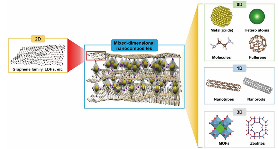
Nanoparticles (NPs) are typically defined as granular materials with at least one dimension at the nanoscale (1-100 nm) in three-dimensional space. From the dimensions of structure and morphology, nanoparticles can be classified into zero dimensional nanomaterials (0D nanomaterials), corresponding to one-dimensional (1D) and two-dimensional (2D) nanomaterials. 0D nanoparticles are subject to size constraints in three-dimensional space, with typical representatives including metal nanoparticles, oxide nanoparticles, sulfide nanocrystals, etc. In addition, based on their composition, nanoparticles can be further subdivided into single component structures (such as pure metals, single oxides) and multi-component structures (such as core-shell structures, alloy nanoparticles, heterostructures, etc.), and their structural complexity directly affects their functional performance.

powder aggregation


What is nanoparticle aggregation and dispersion?


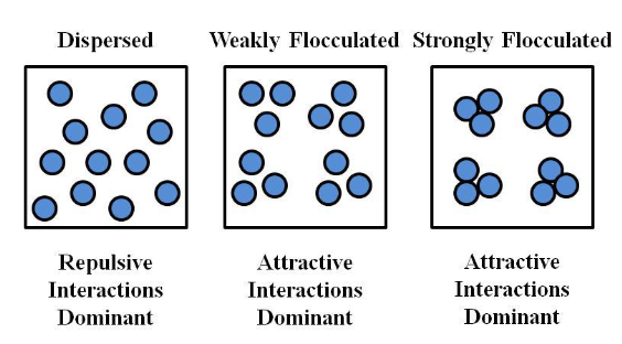
Nanoparticle aggregation: refers to the phenomenon of primary nanoparticles forming larger particle aggregates through physical or chemical forces, usually manifested as size growth and a decrease in specific surface area. Agglomeration can be divided into two categories: reversible agglomeration and irreversible agglomeration. The former can be redispersed through external intervention such as ultrasound or solvent adjustment, while the latter is often caused by consolidation, sintering, or chemical bonding, making it difficult to restore the original dispersed state. Nanoparticle dispersion: refers to the uniform distribution of nanoparticles in liquid, solid, or gas media, maintaining effective spacing between particles, avoiding contact aggregation, and maintaining their monodispersity and high specific surface area state. Effective dispersion is a prerequisite for unleashing its nano effect.

powder aggregation

SAT NANO is a best supplier of nano powder and micro powder in China, if you have any enquiry of nanoparticle aggregation and dispersion, please feel free to contact us at admin@satnano.com


keyboard_arrow_up