dyyseo

Advanced Materials Driving the Future of Low-Altitude Economy: Lightweighting, Performance and Future Manufacturing


In 2026, the low-altitude economy is entering a milestone phase driven by supportive policies, positioning itself as a new strategic pillar industry.


Behind this trillion-yuan market transformation lies a fundamental factor that determines the performance boundaries and commercial success of next-generation aircraft — advanced materials. Industry analysis indicates that advanced materials currently account for approximately 30%–50% of aircraft material costs. As the low-altitude economy expands beyond the RMB 1 trillion market scale, the demand for advanced materials is projected to exceed RMB 500 billion, creating significant opportunities for high-performance composite materials.



1. Lightweighting: A Competition Measured in Every Gram


For low-altitude aircraft, weight is the strictest “accountant.” Unlike traditional fuel-powered aircraft, electric low-altitude aircraft rely on batteries for energy supply.

Every additional kilogram means reduced flight range and lower payload capacity. The industry often refers to the principle that “every kilogram saved can add 10 kilometers of range.” Therefore, every weight reduction in the fuselage, wings, and rotors can translate into longer flight distances, higher payload capacity, or greater safety margins.


Carbon fiber composites are considered the ultimate solution to this challenge. With a density only about one-quarter that of steel while offering tensile strength more than nine times higher, carbon fiber composites can significantly reduce aircraft weight when replacing traditional metal materials. Compared with conventional aluminum alloys, carbon fiber composites can achieve 20%–40% structural weight reduction. Thanks to their outstanding combination of lightweight properties, high strength, high stiffness, corrosion resistance, and fatigue resistance, carbon fiber composites have become an ideal material choice for eVTOL structures and are often referred to as “black gold.”


In eVTOL (electric vertical takeoff and landing aircraft), composite materials are mainly used in structural components and propulsion systems, accounting for approximately 75%–80% of the total aircraft structure. Composite materials represent more than 70% of an eVTOL’s structural composition, with carbon fiber composites accounting for around 90% of the composite materials used. They are widely applied across primary and secondary load-bearing structures and functional components, including fuselages, rotors, wings, battery enclosures, propulsion blades, seats, and various brackets.


Depending on aircraft size and payload requirements, a single passenger eVTOL may require 100–400 kg of carbon fiber composite materials. Industry forecasts suggest that between 2024 and 2030, carbon fiber demand from the eVTOL sector alone will surge from 500 tons to 11,700 tons, representing an average annual growth rate of approximately 69%, with the market expected to expand by 22.5 times within six years.


A cargo drone model has achieved a 40% weight reduction through an all-carbon-fiber fuselage design, extending its flight range to 280 km. The XPeng Voyager X2 adopts carbon fiber materials throughout its airframe to achieve a balance between lightweight design and structural safety, while AutoFlight V2000CG also incorporates high-strength carbon fiber composite technologies in its core structure.
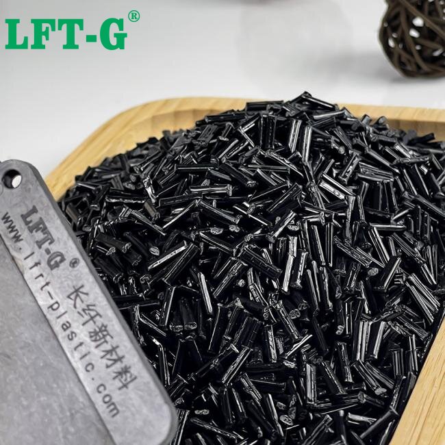


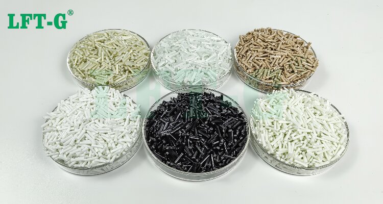
Nylon 12 Carbon Fiber Reinforced


2. Foam Core Materials: The “Invisible Skeleton” Inside Sandwich Structures


Beyond the carbon fiber composite “skeleton” of low-altitude aircraft, foam core materials serve as an indispensable “invisible backbone” within sandwich structures. Their core value lies in providing extremely high specific stiffness and buckling resistance to composite skins while maintaining ultra-low weight, achieving a structural efficiency where “1+1>2.”


Currently, foam core materials used in low-altitude aircraft mainly follow a dual-material landscape dominated by PMI foam and PVC foam, each serving different performance and cost requirements.


PMI foam (Polymethacrylimide foam) is a key core material designed to meet the combined demands of extreme lightweighting, structural rigidity, thermal resistance, and flame-retardant performance. Its primary role is to enable the manufacturing of large-scale integrated sandwich structures, including wings, fuselage sections, and rotor blades. Thanks to its closed-cell microstructure and inherent thermal stability, PMI foam provides a passive safety barrier that helps resist heat penetration while maintaining structural integrity under high-temperature conditions.


In the eVTOL sector, PMI foam core materials have become the dominant choice for high-performance applications. ROHACELL PMI foam developed by Evonik, known for its ultra-lightweight characteristics and high mechanical strength, has already been applied in the design of critical eVTOL structural components. Industry forecasts indicate that a single eVTOL aircraft may require up to 50 kg of PMI foam core materials. The global eVTOL PMI foam market reached approximately USD 250 million in sales in 2025 and is projected to grow to USD 707 million by 2032, representing a compound annual growth rate (CAGR) of 16.0%.


PVC foam core materials, on the other hand, have gained widespread adoption in fixed-wing UAV applications due to their cost advantages. Structural PVC foam features a high closed-cell ratio, excellent mechanical properties, temperature resistance, and chemical corrosion resistance. In the eVTOL field, PVC foam cores are mainly used in non-load-bearing structures such as cargo compartments of cargo aircraft models.


In addition, materials such as PET foam and balsa wood cores are also utilized in specific applications, together forming a diversified core material system for sandwich structures in low-altitude aircraft.


3. Metallic Materials: From “Foundation” to “Critical Structural Support”


Although carbon fiber composites are gaining an increasing share of applications in low-altitude aircraft, metallic materials are far from being replaced. Instead, they continue to play irreplaceable roles in specific areas where strength, durability, reliability, and manufacturability are essential. Aluminum alloys, titanium alloys, magnesium alloys, and aluminum-lithium alloys together form a comprehensive metallic material system that enables lightweight design, high performance, and structural safety for low-altitude aircraft.

Aluminum Alloys: The Foundation Materials of Low-Altitude Aircraft

With advantages including low density (approximately 2.7 g/cm³), excellent corrosion resistance and good manufacturability, aluminum alloys remain among the most widely used structural materials.


With advantages including low density (approximately 2.7 g/cm³), excellent corrosion resistance, and good manufacturability, aluminum alloys remain among the most widely used structural materials in low-altitude aircraft. In the eVTOL sector, aerospace-grade aluminum alloys account for more than 60% of the fuselage structural weight, with the global market reaching approximately RMB 1.95 billion in 2026. High-strength aluminum alloys are widely applied in areas exposed to concentrated loads, including wing joints, tail connections, landing gear, and rotor structures.


According to data from the China Nonferrous Metals Industry Association, aluminum demand from the UAV sector increased by 40% year-on-year in 2025. The GOVY AirCab flying car developed by GAC Group adopts an aerospace-grade aluminum alloy frame. Beyond aircraft structures, aluminum alloys are also widely used in the construction of lightweight runways and intelligent control towers for low-altitude takeoff and landing facilities.


Titanium alloys serve as the “joints and critical components” of aircraft.

Thanks to their excellent strength-to-weight ratio, high-temperature resistance, and corrosion resistance, titanium alloys are widely used in key load-bearing components such as aircraft engines and landing gear, accounting for approximately 15%–20% of eVTOL structural weight. The latest dual-titanium alloy blade disk designs have improved propulsion system efficiency by 15%–20% while extending fatigue life by 40%.


Magnesium alloys are the “hidden champion” in the lightweighting competition.

With a density only around two-thirds that of aluminum alloys, magnesium alloys offer exceptional lightweight advantages. By significantly reducing aircraft weight, magnesium alloys can improve flight range and payload capacity, accelerating their adoption in the low-altitude economy.


In eVTOL applications, components such as integrated arms, battery housings, and motor casings are gradually shifting from aluminum to large-scale magnesium alloy die-cast structures, potentially reducing overall aircraft weight by more than 30%. Magnesium-lithium alloys, with a density approximately half that of aluminum alloys, are becoming a critical solution for high-end aircraft seeking improvements in both endurance and payload capacity, especially as future lightweighting requirements continue to rise.


Aluminum-lithium alloys represent an advanced direction for achieving both strength and lightweight performance.

Primarily used in major load-bearing structures such as wing spars and fuselage frames, aluminum-lithium alloys can reduce weight by approximately 8%–10% compared with traditional aluminum alloys while maintaining structural strength.


As eVTOL commercialization and mass production accelerate, demand for aerospace-grade aluminum alloys, titanium alloys, and nickel-based high-temperature alloys is expected to experience simultaneous growth in both volume and value during the second half of 2026.


4. Special Engineering Plastics and Aramid Materials: The Indispensable “Supporting Roles”


Special engineering plastics also play an essential role in the development of low-altitude aircraft. High-performance nylon, flame-retardant polyester materials, and thermoset composites have already achieved mass production applications in consumer drones, agricultural drones, and other commercial scenarios.


Polyether ether ketone (PEEK) materials have attracted significant attention due to their outstanding combination of lightweight properties, high-temperature resistance, flame retardancy, corrosion resistance, and excellent mechanical performance. PEEK has been applied in various aircraft components, including wheel covers, fairings, seat frames, environmental control system impellers, and wing fasteners. In UAV frames and flying vehicle structural components, PEEK demonstrates significant advantages as a metal replacement material.


Thermoplastic composites based on modified polyamide (PA), polyether ether ketone (PEEK), and other high-performance polymers are seeing increasing adoption in load-bearing components and structural connection parts, driven by the demand for lightweight, integrated, and cost-efficient manufacturing solutions.


Aramid fiber composites offer excellent toughness and impact resistance, making them suitable for applications such as secondary load-bearing structures in helicopters and UAV wing skins. Aramid paper honeycomb cores and sandwich structures provide a combination of ultra-lightweight design, high strength, and impact resistance, and are widely used in aircraft interiors, radomes, and structural components.


By adopting honeycomb composite structures, aircraft manufacturers can achieve approximately 20% localized weight reduction while simultaneously improving fatigue resistance and extending service life.
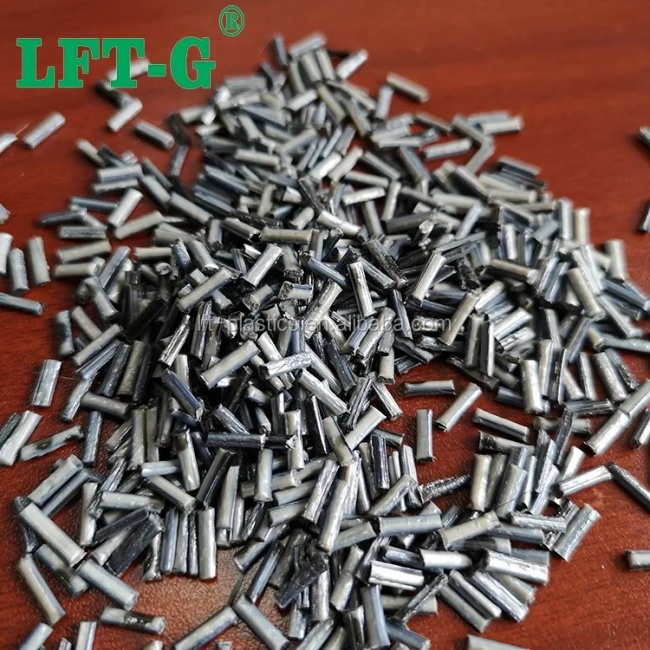


PEEK Carbon Fiber Reinforced


The Future of Low-Altitude Aircraft Lies in Material Integration

The development of the low-altitude economy is not driven by a single perfect material, but by the integration of multiple advanced material systems. Carbon fiber composites provide exceptional lightweight strength, foam cores improve structural efficiency, metallic materials ensure reliability, while high-performance polymers enable lightweight and cost-efficient manufacturing.

As eVTOL aircraft and commercial drones move toward large-scale production, long fiber reinforced thermoplastic composites are expected to play an increasingly important role due to their excellent mechanical performance, impact resistance, design flexibility, and suitability for efficient manufacturing.

The future of low-altitude mobility will be shaped not only by innovative aircraft design, but also by continuous breakthroughs in advanced materials — creating aircraft that are lighter, safer, more efficient, and ready for commercialization.
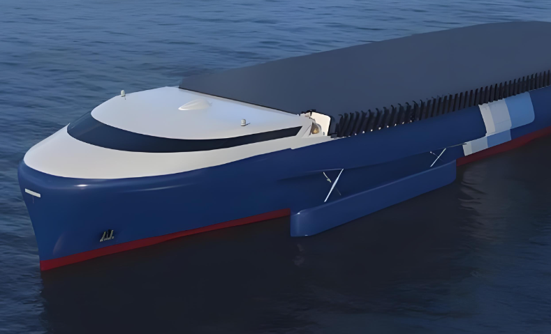

Why Long Fiber Reinforced Thermoplastics Are Replacing Metals in Marine Applications | LFT-G
MARINE COMPOSITE MATERIALS

Why Long Fiber Reinforced Thermoplastics Are Replacing Metals in Marine Applications

Discover how Long Fiber Reinforced Thermoplastics (LFT) provide corrosion resistance, lightweight performance, high mechanical strength and long-term durability for demanding marine engineering applications.

Key Takeaway: In marine environments, material selection is not only about strength and weight. Corrosion resistance, service life, maintenance requirements and total lifecycle cost can be equally important. This is where fiber-reinforced thermoplastic composites offer a compelling alternative to traditional metals.

Introduction: Why Marine Engineering Needs New Materials

Metals have been the foundation of modern industrial development for centuries. Steel, aluminum and titanium alloys have enabled the construction of ships, offshore platforms, marine infrastructure and advanced industrial equipment.

However, when traditional metals are exposed to harsh marine environments for extended periods, they face one fundamental challenge: corrosion.

Seawater combines salt, oxygen, moisture and complex electrochemical conditions, creating one of the most demanding environments for engineering materials. Chloride ions can accelerate localized corrosion, while continuous exposure can increase maintenance requirements and shorten component service life.

For offshore wind power, shipbuilding, seawater systems, marine equipment and coastal infrastructure, corrosion is more than a material problem. It can directly influence operational safety, maintenance costs, equipment reliability and overall lifecycle economics.

As a result, engineers are increasingly looking for corrosion-resistant composite materials that can reduce dependence on traditional metal components.

Why Do Metals Corrode in Marine Environments?

From a thermodynamic perspective, most refined metals exist in a relatively high-energy state compared with their naturally occurring mineral forms.

During metal production, significant energy is required to transform metal oxides and ores into refined metals. Over time, metals naturally tend to return toward more stable oxidized states through chemical and electrochemical reactions.

In marine environments, seawater acts as an effective electrolyte. The combination of oxygen, water and chloride ions creates favorable conditions for electrochemical corrosion.

This is why corrosion protection remains one of the most important challenges in marine engineering and offshore applications.

The Hidden Corrosion Risks of Stainless Steel

Stainless steel is widely used because its chromium-rich passive layer provides excellent corrosion resistance under many conditions. However, stainless steel should not be interpreted as completely corrosion-proof.

In marine environments, stainless steel can still experience several localized corrosion mechanisms.

Pitting Corrosion

Localized breakdown of the passive layer can create small corrosion sites that gradually develop into deep pits. These pits may penetrate significantly into the material while leaving relatively little visible damage on the surface.

Crevice Corrosion

Narrow gaps around fasteners, mechanical joints, seals and overlapping components can create oxygen-depleted conditions. These areas can become highly susceptible to localized corrosion.

Stress Corrosion Cracking

The combination of tensile stress and a corrosive marine environment can contribute to stress corrosion cracking in susceptible alloys, creating additional challenges for long-term structural reliability.

The challenge is not simply that metal corrodes. In many marine applications, corrosion can develop in areas that are difficult to inspect, repair or recoat.

From Polymer Stability to Engineering Performance

Plastics are often discussed in the context of environmental persistence. However, from an engineering perspective, the chemical stability of polymers can provide a major performance advantage.

When thermoplastic polymers are reinforced with long glass fibers or carbon fibers, their mechanical properties can be significantly improved, creating fiber-reinforced thermoplastic composites.

Unlike traditional metals, the polymer matrix does not undergo the same electrochemical corrosion mechanism responsible for rust and many forms of metal degradation.

This makes fiber-reinforced thermoplastics attractive for applications where resistance to seawater, salt spray and chloride-rich environments is important.

Why Long Fiber Reinforced Thermoplastics Are Ideal for Marine Applications


Long Fiber Reinforced Thermoplastics (LFT) combine the processing advantages of thermoplastics with the mechanical reinforcement provided by long glass fibers or carbon fibers.

This combination allows engineers to develop lightweight structural components that provide high strength, impact resistance and durability while offering excellent resistance to corrosion.

01. Corrosion Resistance

LFT materials do not rust and provide excellent resistance to seawater and chloride-rich environments, helping reduce corrosion-related maintenance.

02. Lightweight Performance

Long glass fiber and carbon fiber reinforced thermoplastics offer excellent strength-to-weight ratios, making them attractive alternatives to heavier metal components.

03. High Mechanical Strength

Long fibers improve load transfer within the polymer matrix and can provide high tensile strength, stiffness and impact resistance.

04. Manufacturing Efficiency

Thermoplastic composite materials can be processed using injection molding and other high-efficiency manufacturing technologies, supporting scalable production.

Long Fiber Reinforced Thermoplastics vs. Traditional Metals

The right material depends on the application. However, for marine components exposed to corrosive environments, LFT composites offer several important advantages.

Property Traditional Metals Fiber-Reinforced Thermoplastics
Corrosion Resistance Requires material selection and protection systems Excellent resistance to seawater and chloride environments
Weight Generally higher Lightweight
Strength-to-Weight Ratio Good Excellent for many structural applications
Maintenance May require coating, inspection and corrosion control Reduced corrosion-related maintenance requirements
Design Flexibility Dependent on machining and forming processes High design flexibility through molding technologies
Large-Scale Production Well established Highly suitable for automated thermoplastic processing

Marine Applications of Fiber-Reinforced Thermoplastics

The combination of corrosion resistance, lightweight performance and mechanical strength makes fiber-reinforced thermoplastics suitable for a growing range of marine and offshore applications.

Offshore Energy

  • Offshore wind turbine components
  • Oil and gas platform components
  • Offshore equipment housings
  • Subsea equipment components

Marine Equipment

  • Pump components
  • Valve components
  • Protective housings
  • Seawater cooling system components

Shipbuilding

  • Lightweight structural components
  • Corrosion-resistant components
  • Interior systems
  • Equipment housings

Coastal Infrastructure

  • Water treatment equipment
  • Seawater handling systems
  • Infrastructure components
  • Corrosion-resistant structural parts

Glass Fiber vs. Carbon Fiber Reinforced Thermoplastics

Both Long Glass Fiber Reinforced Thermoplastics (LGF) and Long Carbon Fiber Reinforced Thermoplastics (LCF) can be used to develop lightweight structural components, but their performance profiles are different.

Long Glass Fiber Reinforced Thermoplastics

LGF thermoplastics provide an attractive balance of mechanical strength, impact resistance, weight reduction and cost efficiency. They are suitable for many industrial and marine components where high performance and cost effectiveness are both important.

Long Carbon Fiber Reinforced Thermoplastics

LCF thermoplastics provide higher stiffness and excellent strength-to-weight performance, making them suitable for applications where structural performance and weight reduction are particularly important.

The Material Selection Dilemma: Space vs. Ocean

There is no universal material that is ideal for every engineering environment. Material selection must always consider temperature, mechanical loading, chemical exposure, manufacturing requirements, cost and expected service life.

SpaceX's Starship program provides an interesting example. Stainless steel was selected for Starship because of its performance under cryogenic conditions, resistance to extreme aerodynamic heating, manufacturing efficiency and cost advantages.

However, aerospace and marine engineering present fundamentally different challenges.

Space is a vacuum. The ocean is a continuous electrochemical environment.

A material that is highly competitive for spacecraft does not necessarily provide the best lifecycle value for a structure exposed to seawater for decades.

Why Lifecycle Cost Matters in Marine Engineering

Initial material price is only one part of the total cost of an engineering component. In marine applications, designers must also consider inspection, coating, replacement, downtime and maintenance over the entire service life.

A corrosion-resistant composite component can potentially reduce the need for corrosion protection and maintenance, helping improve the overall lifecycle economics of marine equipment.

This is particularly important for components installed in difficult-to-access locations, where inspection and replacement can be expensive or operationally disruptive.

The Future of Marine Engineering: Lightweight and Corrosion-Resistant Composites

The future of marine engineering is not about eliminating metals entirely. Different materials will continue to serve different engineering requirements.

However, as industries increasingly focus on lightweighting, energy efficiency, durability and lower lifecycle costs, advanced composite materials are becoming an increasingly important part of material selection strategies.

Long Fiber Reinforced Thermoplastics offer a compelling combination of corrosion resistance, lightweight performance, mechanical strength and manufacturing efficiency.

For marine and offshore applications where long-term exposure to seawater is a critical design factor, fiber-reinforced thermoplastic composites can provide a reliable alternative to selected metal components.

By combining advanced thermoplastic matrices with long glass fiber and long carbon fiber reinforcement, LFT-G develops high-performance composite materials designed to support the next generation of lightweight and durable engineering solutions.

Frequently Asked Questions

Why are composite materials used in marine applications?

Composite materials offer excellent corrosion resistance, lightweight performance, high strength and long-term durability, making them suitable for demanding marine environments.

What are Long Fiber Reinforced Thermoplastics?

Long Fiber Reinforced Thermoplastics are advanced thermoplastic composites reinforced with long glass fibers or carbon fibers to improve strength, stiffness, impact resistance and dimensional stability.

Can LFT materials replace metals in marine applications?

Depending on the application, LFT materials can replace selected metal components where corrosion resistance, weight reduction, mechanical performance and manufacturing efficiency are important.

Are glass fiber reinforced thermoplastics resistant to seawater?

Glass fiber reinforced thermoplastics provide strong resistance to seawater and chloride-rich environments because the thermoplastic matrix does not undergo the electrochemical corrosion mechanism associated with metals.

Looking for High-Performance Marine Composite Materials?

LFT-G develops long glass fiber and long carbon fiber reinforced thermoplastic materials for demanding industrial applications. Contact our technical team to discuss a customized material solution for your marine or offshore project.

Contact LFT-G

3 Critical Hidden Defects Inside High-Filled Thick-Wall Plastic Parts

High glass fiber and mineral-filled plastics are widely used in automotive, appliance, and industrial structural applications because they provide excellent stiffness, strength, and dimensional stability.

However, thick-wall molded components made from highly filled plastics are highly susceptible to hidden internal defects, including internal voids, delamination, and cold slugs.

Because these defects are hidden beneath the surface, they often cannot be detected through normal appearance inspection. During actual operation, internal defects may become stress concentration areas, causing cracks, leakage, sudden failure, and expensive batch rejection.

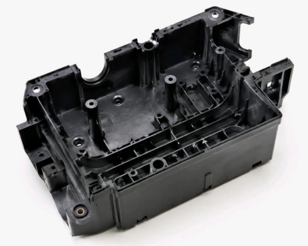
Hidden internal defects in high-filled thick-wall plastic parts

Table of Contents

  • Why Are Thick-Wall Highly Filled Plastic Parts More Prone to Internal Defects?
  • Internal Voids / Shrinkage Cavities
  • Delamination / Interlayer Separation
  • Cold Slugs / Internal Dark Spots

1. Why Are Thick-Wall Highly Filled Plastic Parts More Prone to Internal Defects?

Compared with highly filled plastics, conventional unfilled plastics generally have better flowability and more uniform shrinkage behavior, resulting in fewer molding risks.

However, after adding large amounts of glass fiber or mineral fillers, melt viscosity increases significantly. The material becomes more difficult to flow, fill, and pack during injection molding.

Two Major Challenges of Thick-Wall Structures

1. Longer Flow Paths and Uneven Cooling

During injection molding, the molten plastic contacting the cooler mold surface solidifies first, forming a hardened outer skin. Meanwhile, the internal material cools much slower, creating a large temperature difference between the surface and the core.

2. Greater Cooling Shrinkage in Thick Sections

Thick sections experience larger volume shrinkage during cooling. Maintaining sufficient packing pressure and achieving uniform material fusion become much more difficult.

When melt flow, heat transfer, or molecular bonding becomes unbalanced, hidden internal defects may form inside the component.

These defects are often invisible during conventional visual inspection and usually require destructive section analysis or advanced non-destructive inspection methods such as CT scanning.

2. Internal Voids / Shrinkage Cavities: Hidden Hollow Areas Inside Structural Parts

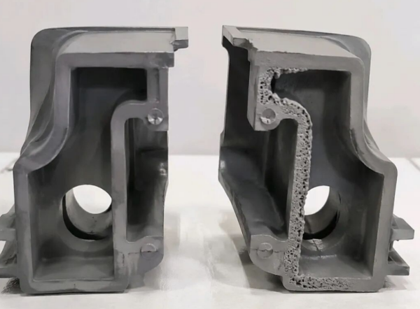
Internal voids and shrinkage cavities in thick wall plastic parts

1. Defect Characteristics

The external surface of the component may appear completely normal without visible defects. However, after cutting open the thick-wall section, irregular internal voids or cavities can be observed.

These internal voids reduce the effective load-bearing area and significantly weaken structural performance. Under mechanical stress, components may crack or fracture, while sealing parts may develop leakage problems.

2. Formation Mechanism

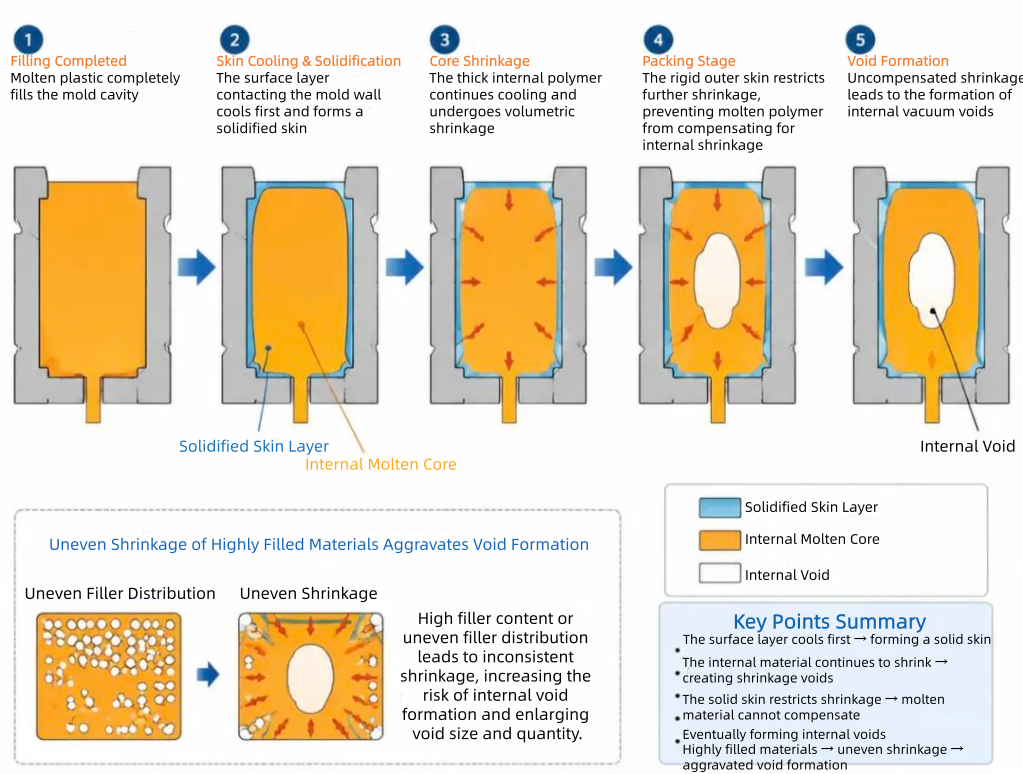
After molten plastic completely fills the mold cavity, the material contacting the mold wall cools and solidifies first, creating a rigid outer shell.

The internal molten plastic continues cooling and shrinking. However, the hardened outer layer restricts further contraction.

During the packing stage, insufficient molten material is available to compensate for shrinkage, eventually forming internal vacuum voids.

For highly filled materials, uneven shrinkage between the polymer matrix and fillers can further increase the risk of void formation.

Formation mechanism of internal voids during injection molding

3. Main Causes

  • Excessive local wall thickness or sudden wall thickness transitions.
  • High material shrinkage rate.
  • Insufficient injection pressure or packing pressure.
  • Gate location too far away from thick-wall areas.
  • Poor mold venting or improper cooling channel design.

4. Improvement Solutions

① Part Design Optimization

  • Maintain uniform wall thickness throughout the component.
  • Add hollow structures, ribs, or material-reduction features in thick areas to reduce excessive material accumulation.

② Material Selection Optimization

  • Select highly filled plastics with low shrinkage and good flowability.
  • Ensure uniform filler dispersion to improve dimensional stability and reduce internal stress.

③ Injection Molding Process Optimization

  • Increase melt temperature and mold temperature to slow premature surface solidification.
  • Extend packing time and apply multi-stage packing pressure to provide continuous material compensation during cooling shrinkage.

④ Mold Design Optimization

  • Position the gate closer to thick-wall areas to shorten flow paths and reduce pressure loss.
  • Add venting channels near thick sections to improve gas removal.
  • Apply conformal cooling channels to achieve more uniform mold temperature distribution.

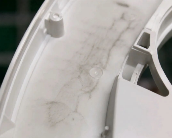
3. Delamination / Interlayer Separation: Hidden Layers That Dramatically Reduce Mechanical Strength

Delamination and interlayer separation defects in reinforced plastic parts

1. Defect Characteristics

A cross-sectional inspection reveals clear layered patterns, indicating that the material layers have failed to properly fuse together.

The layers can separate easily along the weak interface even under relatively low mechanical stress.

This defect causes a significant reduction in impact strength and flexural strength, making it one of the most severe internal defects in structural plastic components.

2. Formation Mechanism

Highly filled plastics have higher melt viscosity and poorer flowability compared with unfilled materials. During mold filling, the melt may split into multiple flow fronts.

When different melt streams with different temperatures and flow speeds meet, polymer chains may fail to properly interpenetrate and fuse together.

After cooling, a permanent separation layer is formed inside the part.

High injection speeds can generate jetting effects and unstable cavity flow, while melt backflow during filling can further intensify delamination.

3. Main Causes

  • Melt temperature and mold temperature are too low, resulting in poor material flowability.
  • Multiple gates create separated flow fronts with excessive merging angles.
  • Injection speed is too high, causing jetting defects.
  • Insufficient drying of plastic materials allows moisture to prevent proper fusion between melt layers.

4. Improvement Solutions

① Increase Temperature to Improve Flowability

  • Increase both barrel temperature and mold temperature to reduce melt viscosity and promote better fusion between flow fronts.

② Optimize Mold Runner and Gate Design

  • Reduce the number of gates where possible.
  • Minimize the angle between converging melt flows.
  • Design smooth runner transitions to prevent jetting and unstable filling behavior.

③ Adjust Injection Parameters

  • Apply multi-stage injection with controlled low-speed filling at critical areas.
  • Prevent jetting and avoid unstable melt backflow during filling.

④ Improve Material Preparation

  • Thoroughly dry raw materials before molding to remove moisture.
  • Properly extend the packing stage and use holding pressure to enhance interlayer bonding.

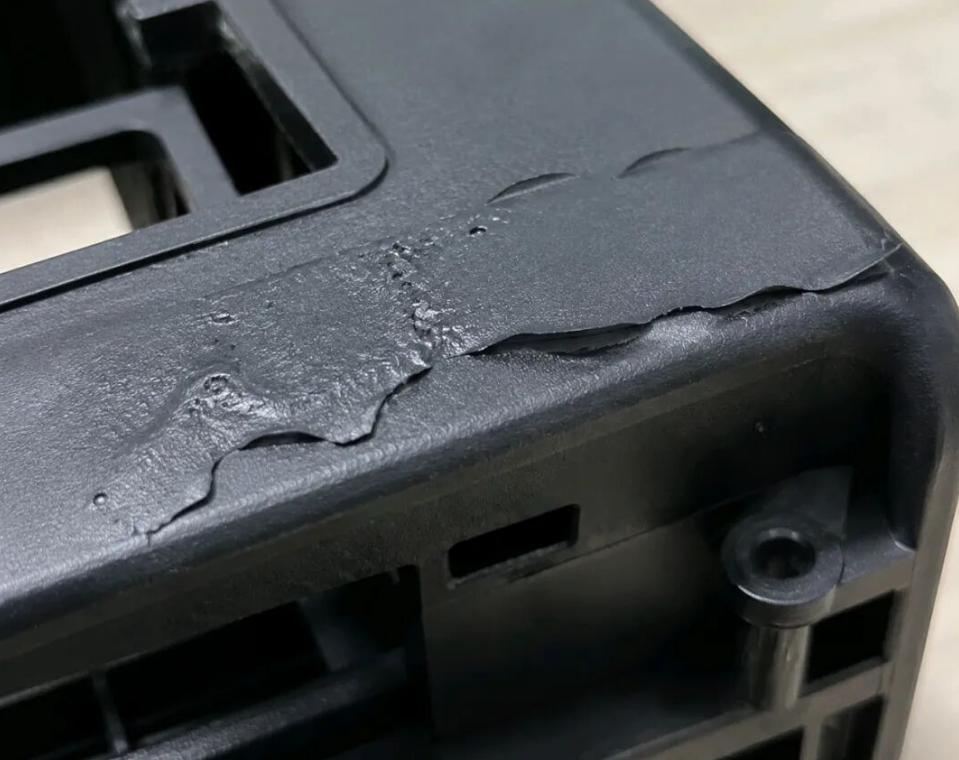
4. Cold Slugs / Internal Dark Spots: Appearance Defects Combined With Hidden Stress Concentration Areas

Cold slug and internal dark spot defects in injection molded plastic parts

1. Defect Characteristics

Dark, dull, or matte streaks and spots may appear on the surface or inside the component.

These defects are usually caused by uneven filler distribution, unstable melt flow, or insufficient fusion between different material regions.

Besides affecting appearance, these areas often have weaker bonding strength and become potential stress concentration zones, reducing the overall reliability of the component.

2. Formation Mechanism

A portion of low-temperature material accumulated in the runner system or at the front end of the barrel may enter the mold cavity together with normal molten plastic flow.

Because the cold material and hot melt have significant differences in temperature and viscosity, complete fusion cannot be achieved.

The cold slug becomes trapped inside or near the surface of the molded part, creating dark-colored spots or irregular marks.

For thick-wall components, melt flow often splits into multiple streams, increasing the possibility of cold material being trapped and forming internal defects.

3. Common Causes

  • Melt temperature or mold temperature is too low.
  • Injection speed is too slow, allowing the melt front to cool prematurely.
  • Excessive runner branching increases unnecessary melt convergence areas.
  • Poor venting causes trapped gas around cold material regions.

4. Improvement Solutions

① Increase Temperature to Reduce Thermal Differences

  • Increase barrel temperature and mold temperature to improve melting conditions and promote better fusion.

② Optimize Injection Speed

  • Increase injection speed appropriately to shorten filling time and reduce premature cooling of the melt front.

③ Improve Mold Design

  • Simplify runner systems to reduce unnecessary flow merging points.
  • Add cold slug wells to capture low-temperature material before it enters critical areas.

④ Additional Optimization

  • Improve venting at melt flow convergence areas.
  • Add appropriate flow modifiers when necessary to enhance melt compatibility and processing performance.

Conclusion: Preventing Internal Defects Requires Material, Process, and Mold Optimization

For high-filled thick-wall plastic components, internal defects are often invisible during conventional inspection but can seriously affect long-term reliability, mechanical performance, and product safety.

A successful solution requires comprehensive optimization across material selection, part design, injection molding parameters, and mold structure.

By selecting high-performance reinforced thermoplastics with controlled shrinkage, optimizing processing conditions, and improving mold design, manufacturers can significantly reduce the risks of voids, delamination, and cold slug defects.

For lightweight structural applications and metal replacement projects, controlling internal quality is essential to achieving stable performance and reliable production.

Frequently Asked Questions About High-Filled Plastic Defects

Why do glass fiber reinforced plastics develop internal voids?

Internal voids usually occur because thick sections experience uneven cooling shrinkage. When the outer surface solidifies before the core, insufficient packing compensation can create internal cavities.

Can internal defects in injection molded parts be detected visually?

No. Many internal defects such as voids and delamination are hidden beneath the surface and cannot be identified through normal appearance inspection. Advanced inspection methods such as CT scanning or section analysis are often required.

How can long fiber reinforced thermoplastics improve structural reliability?

Long fiber reinforced thermoplastics provide improved load transfer, higher impact resistance, better dimensional stability, and reduced warpage compared with conventional short fiber reinforced materials.

Need Reliable Materials for Thick-Wall Structural Components?

High-filled plastic parts require more than simply increasing filler content. Fiber length retention, filler dispersion, shrinkage control, and processing stability are critical factors for achieving reliable structural performance.

LFT-G develops long fiber reinforced thermoplastic solutions including PP-LGF, PA-LGF, PA-LCF, PPS-LGF, and other high-performance composites for automotive, industrial, appliance, and lightweight structural applications.

Explore LFT-G Materials

Why Are Leading Manufacturers Replacing Metal with Modified Plastics?

In 2026, the global modified plastics market is expected to exceed USD 19.476 billion, growing at an annual rate of 8.2%.

Behind this rapidly expanding market is a continuous material revolution: replacing traditional metals with advanced engineering plastics.

Key Conclusion

Whether in aerospace equipment, automotive components, or electronic products, material selection is never simply about choosing the hardest material.

The best solution depends on three key factors:

Performance requirements + Application conditions + Overall cost efficiency

1. Metal vs. Engineering Plastics: The Natural Toughness of Metals

Three Major Limitations of Traditional Metal Parts

Limitation Specific Performance Cost Impact
Heavy Weight Density is 3–5 times higher than engineering plastics Higher transportation and assembly costs
Difficult Processing Requires cutting, stamping, welding and other processes Higher machining and labor costs
Corrosion Risk Requires coating and anti-rust treatment Additional maintenance costs

Why Ordinary Plastics Cannot Replace Metals

  • Temperature resistance: deformation and performance loss may occur under long-term heat exposure.
  • Low-temperature performance: brittleness and cracking may occur under cold impact conditions.
  • Strength and rigidity: insufficient mechanical performance for structural applications.
  • Dimensional stability: thermal expansion affects precision applications.

2. Three Core Application Scenarios of Modified Plastics

Scenario 1: Household Appliances — PA and PET Reinforced Materials

Household appliances require excellent rigidity, impact resistance, dimensional stability and electrical safety performance.

Performance Standard PA/PET Glass Fiber Reinforced PA/PET Improvement
Tensile Strength 30–40 MPa 80–140 MPa 2–4 times higher
Heat Distortion Temperature 60–80°C 120–160°C +40–70°C
Impact Resistance Average Excellent Multiple improvement
Key Insight:
When glass fiber content reaches 20–30%, the material achieves excellent rigidity and heat resistance. However, excessive fiber content may increase brittleness and reduce toughness.

Scenario 2: Electronic Connectors — PBT Materials as Industry Solutions

Safety Requirement Requirement Modified PBT/PA Performance
UL94 Flame Rating V-0 level Can achieve V-0 flame retardancy
CTI Value ≥600V for high voltage applications Special formulations can reach 600V+
Temperature Range -40°C to 200°C Covered by modified materials
Electrical Stability Long-term insulation Stable electrical performance

Scenario 3: Automotive Engine Components — PPS and High Performance PA

Comparison Aluminum Alloy Modified Plastics (PPS/PA) Advantage
Weight 100% ≈60% Up to 40% weight reduction
Cost 100% ≈50% Lower overall cost
Processing Multiple processes Injection molding Higher efficiency
Durability Requires protection Corrosion resistant Reduced maintenance
Modified PPS and PA materials can combine multiple functions into one injection-molded component, reducing secondary machining, drilling and finishing processes.

3. Industry Insights

There Is No Perfect Material — Only the Best Material for Each Application

Modified plastics are not simply replacing metals everywhere. Instead, engineers select the most suitable material based on different working conditions.

  • Home Appliances: insulation, appearance and durability
  • Electronic Connectors: electrical safety and dimensional stability
  • Automotive Components: lightweight design, heat resistance and reliability
Every material selection decision is a balance between:

Performance and Cost.

Conclusion

With industries continuously pursuing lightweight design, higher efficiency and cost optimization, modified engineering plastics are becoming an increasingly important alternative to traditional metals.

The future of material selection is not about whether plastics can completely replace metals, but about finding the most suitable material solution for every application.

Synthesis of Carbon Quantum Dots

The synthesis of carbon quantum dots can be mainly divided into two categories: top-down method and bottom-up method. Through the pre-treatment, preparation, and subsequent processing, carbon quantum dots can be controlled in size, passivated on the surface, doped with heteroatoms, and nanocomposites to meet the requirements.

Carbon Quantum Dots

Top-down approach
Top down method: laser ablation method, electrochemical method, arc discharge method.


arc discharge
Dr. Xu synthesized blue and yellow fluorescent carbon nanoparticles using carbon ash as a carbon source using arc discharge method. Bottini et al. synthesized yellow green fluorescent carbon quantum dots using single-walled carbon nanotubes as carbon sources. Sun et al. prepared carbon quantum dots with nanocomposite particle sizes smaller than 10 nm, which can be used for photoelectric conversion.
The arc discharge method has a relatively low yield, complex purification, difficult product collection, high oxygen content, and does not require surface modification. Its luminescence mechanism can be similar to that of carbon nanotubes.


Laser ablation method
Dr. Sun prepared fluorescent carbon quantum dots using carbon as the target through laser ablation.
Dr. Hu synthesized carbon quantum dots with simultaneous surface functionalization using laser ablation method in one step.
The laser ablation method requires expensive instruments and the addition of organic solvents to alter the surface state in order to produce fluorescent carbon quantum dots.


Electrochemical method
Electrochemical oxidation method refers to the method of preparing carbon quantum dots by oxidizing carbon source W using electrochemical methods. Zhou et al. obtained carbon quantum dots by electrochemical oxidation of multi walled carbon nanotubes (MwCNTs).
Electrochemical methods have unique advantages in surface structure analysis and luminescence mechanism research, including low material cost, mild conditions, simple post-treatment.


Bottom-up approach
Bottom up method: Organic carbonization method, microwave method, hydrothermal method, combustion method, ultrasonic treatment method, etc.


Organic carbonization method
Organic carbonization method: Carbon quantum dots capable of emitting fluorescence can be obtained by carbonizing organic precursors, and water-soluble/oil soluble carbon quantum dots with surface functionalization can be prepared. Organic carbonization methods can be divided into two categories: heating carbonization and acid dehydration carbonization. This method can change the performance of carbon quantum dots by selecting different carbonization precursors or different surface coating agents


Microwave method
Microwave refers to electromagnetic waves with a wavelength frequency between 300 MHz and 300 GHz. The characteristics of microwave are energy concentration, uniformity, high efficiency, and short reaction time. Different carbon sources such as sucrose, graphite oxide (GO), glucose, chitosan, polyethylene glycol, dimethylformamide (DMF), etc. can be selected to prepare corresponding carbon quantum dots.


Hydrothermal method
Synthesize substances in a reactor using water as a solvent under high temperature and pressure conditions. Its extension method is solvothermal method using organic solvents. The hydrothermal preparation process is relatively simple and easy to control. Simultaneously reacting in a confined space can prevent the volatilization of organic matter. The properties of carbon quantum dots produced vary depending on the solvent used.


Combustion method
The process of preparing carbon quantum dots by combustion method is simple to operate, requires low equipment requirements, and has strong repeatability, but the particle size distribution of the product is difficult to control.
Ultrasonic treatment method


Dr. Li added activated carbon to hydrogen peroxide water to form a black suspension. The suspension diluted by ultrasound treatment at room temperature is then vacuum dialyzed using a cellulose membrane to remove non fluorescent substances. Functionalized carbon nanoparticles (FCNPs) obtained after filtration. The ultrasonic treatment method for preparing carbon quantum dots requires low equipment requirements, simple operation, low cost, high yield, and low energy consumption.
For application or mechanism research, it is necessary to control the size of carbon quantum dots. Currently, the common method is to prepare carbon quantum dots in nanoreactors. The organic starting material is absorbed into a porous nanoreactor through capillary forces, and the organic starting material is cracked in the nanoreactor to remove the nanoreactor and obtain carbon quantum dots.
Surface passivation and functionalization


The quantum efficiency of carbon quantum dots without surface passivation is usually very low. In order to meet specific application needs, people passivate and functionalize carbon quantum dots through covalent binding, coordination, π - π interaction, sol gel interaction and other ways. Functionalization of carbon quantum dots can improve both their optical and physicochemical properties.


Heteroatom doping
Doping with heteroatoms is commonly used to regulate the luminescence of substances. Common heteroatoms include nitrogen (N), sulfur (S), phosphorus (P), silicon (Si), etc. Nitrogen (N) doping can significantly enhance photoluminescence, and the emission intensity is related to nitrogen content; Silicon (Si) doped carbon quantum dots can exhibit a specific response to H2O2.
Composite of carbon quantum dots
Carbon quantum dot composites can combine their fluorescence properties with the electrical, magnetic, optical and other properties of inorganic nanoparticles to meet the needs of different application fields. According to the properties of composite materials, they can be divided into two types: precious metal composites (such as Ag) and semiconductor composites (such as TiO2, Fe2O3, Cu2O, etc.).


The Application of Carbon Quantum Dots
Carbon quantum dots have many excellent properties such as strong photoluminescence, strong electron transfer ability, and good biocompatibility, and have enormous potential application value in fields such as biology, medicine, chemical engineering, and electronics

CQD
Bioimaging
The strong luminescence and good biological low toxicity of carbon quantum dots can be used to replace semiconductor quantum dots and organic dyes. Compared with traditional cell markers, their biggest advantage is multi-color luminescence, which is beneficial for researchers to control and select excitation and emission wavelengths according to different imaging needs. With the deepening of research, selective cell targeting of carbon quantum dots has broad application prospects in the field of biological imaging in the future.


Disease treatment
Carbon quantum dots can serve as photosensitizers for certain specific tumors, while carbon quantum dots clustered in specific areas can inhibit the growth of cancer cells through specific wavelength irradiation. Researchers also use it as a nanocarrier and tracker to monitor the delivery process of drugs or genes. By monitoring the fluorescence signal of carbon quantum dots, the delivery effect of drugs can be inferred, thereby optimizing the injection method and dosage of drugs.


Luminescent materials
Due to its excellent optoelectronic properties, carbon quantum dots can be used for photoelectric conversion. Mirtchev et al. prepared carbon quantum dot sensitized titanium dioxide solar cells.


Photocatalytic applications
The surface of carbon quantum dots has abundant functional groups and excellent electron transfer ability, which gives them excellent photocatalytic and electrochemical catalytic performance. Yu et al. prepared carbon quantum dots P25 TiO2 nanocomposites using a one-step hydrothermal method. Carbon quantum dots serve as electron storage pools and can effectively promote the catalytic hydrogen generation of P25 TiO2 under UV irradiation.


Chemical sensing
The low toxicity, biocompatibility, and photostability of carbon quantum dots can be used to detect molecules such as metal ions, metals, and anions.


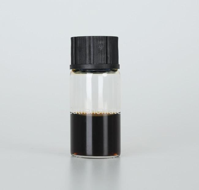
Fluorescent ink
Carbon quantum dots can emit significant fluorescence under ultraviolet light irradiation and have strong photostability, making them used as fluorescent inks. Gao et al. printed colorless carbon quantum dots on Paper Cuttings for anti-counterfeiting ink and information encryption.


SAT NANO is one of the best supplier of CQD carbon quantum dots nanoparticle in China, if you have any interesting, please feel free to contact us at admin@satnano.com


Quantum dots

(QDs) refer to semiconductor nanoparticles with a size smaller than the Bohr radius of the exciton and exhibiting quantum confinement effects. Due to the quantum confinement effect, the fluorescence emission of quantum dots is related to their diameter and chemical composition. By compounding with semiconductor surfaces, their optical and photochemical properties can be enhanced. Traditional quantum dots are mostly composed of heavy metal elements. Although their excellent performance has been widely used in fields such as biological imaging, electrochemistry, and energy conversion, heavy metal elements can cause environmental pollution and affect the health of organisms.

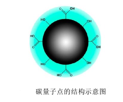
Carbon Quantum Dots (CQDs) typically refer to monodisperse spherical nano carbon materials with a size of less than 10nm, composed of sp2/sp3 carbon core and outer oxygen/nitrogen functional groups. It has excellent performance similar to traditional semiconductor quantum dots, but can effectively overcome the defects of high toxicity and poor biocompatibility. It has a wide range of sources, is easy to synthesize, and is easy to functionalize, making it an ideal substitute material for traditional semiconductor quantum dots.


Chemical structure
Carbon quantum dots are usually spherical particles with a diameter of less than 10nm, composed of sp2/sp3 carbon clusters with amorphous or nanocrystalline structures. Research has found that the structure and physicochemical properties of carbon quantum dots can be selectively altered by introducing different surface defects, doping with heteroatoms, and functional groups.

Carbon Quantum Dots (CQDs)

Optical properties of carbon quantum dots
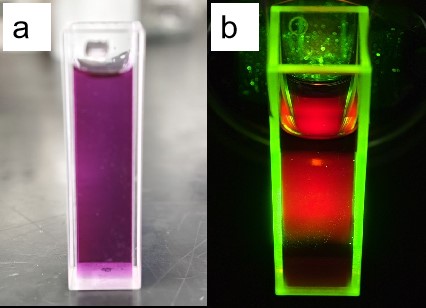
Carbon quantum dots have various excellent optical properties, such as optical absorption, photoluminescence, chemiluminescence, and electrochemiluminescence. These optical properties are the foundation for the application of carbon quantum dots in multiple fields.


Optical absorption
The π - π * transition of C=C bond enables carbon quantum dots to have strong optical absorption in the ultraviolet region and can extend to the visible light region. Some carbon quantum dots will also undergo n - π * transitions at the C=O bond. The absorption spectrum can be adjusted by introducing functional groups and surface passivation.


Photoluminescence
The quantum effects of carbon quantum dots of different sizes are caused by different emission traps on the surface, and effective surface passivation is a necessary condition for carbon quantum dots to have strong photoluminescence. Different surface passivation can achieve the desired photoluminescence performance. In addition, the photoluminescence of carbon quantum dots is also pH dependent.


Upconversion luminescence
Upconversion luminescence (UCPL) refers to the optical phenomenon in which a substance simultaneously absorbs two or more photons, indicating an emission wavelength smaller than the excitation wavelength (anti Stokes emission). Research suggests that upconversion luminescence originates from the transition from high-energy π orbitals to σ Orbital electron relaxation may be caused by leakage from the secondary diffraction part of the monochromator in a fluorescence spectrometer.


Chemiluminescence
Carbon quantum dots exhibit chemiluminescence (CL) when coexisting with MnO4- or Ce4+. The coincidence of radiation caused by electrons generated through chemical reduction and holes generated by thermal excitation is believed to be the reason for chemiluminescence.


Electrochemiluminescence
Carbon quantum dots exhibit electrochemiluminescence (ECL) properties. Under the action of voltage, the electron transfer generated by the oxidation-reduction state of carbon quantum dots annihilates, forming an excited state, which generates an electrochemiluminescence signal during the relaxation process of returning to the ground state.


Electronic transfer performance
The excited states and related transient phenomena of carbon quantum dots are related to fluorescence emission and redox processes. The performance of photo induced electron transfer (PET) is the foundation for energy conversion and catalytic applications of carbon quantum dots. Research has found that the electron transfer performance of carbon quantum dots is mainly influenced by the doping of carbon nuclei, functional groups, and heteroatoms.


Biological performance
Carbon quantum dots have significantly higher biocompatibility than other nanomaterials. Research has shown that most pure carbon quantum dots and surface passivated carbon quantum dots have no significant cytotoxicity. In a few cases, surface passivation and functionalization may lead to lower biological toxicity of carbon quantum dots.


SAT NANO is the supplier fo carbon quantum dots in China, we can offer blue and green fluorescence, if you have any interesting, please feel free to contact us at admin@satnano.com

Silicon carbide particle reinforced aluminum matrix composite material, abbreviated as SiCp/Al composite material, refers to the addition of silicon carbide particles (SiCp) to aluminum matrix alloys to form a composite material with high strength, high stiffness, and high heat resistance. This composite material has been widely used in fields such as aerospace, shipbuilding, vehicles, electronic devices, etc. due to its high corrosion resistance and wear resistance. In addition, the addition of silicon carbide particles can also improve the thermal conductivity of aluminum based materials, enabling them to withstand applications under high temperature conditions.

Silicon carbide particle reinforced aluminum matrix composites have advantages such as high strength, high stiffness, high heat resistance, and high corrosion resistance, and are commonly used in aerospace, automotive manufacturing, military and other fields.

In the field of aerospace, silicon carbide particle reinforced aluminum matrix composites are commonly used in the manufacturing of engine nozzles, turbine blades, flight control systems, missile casings, and other components, which can improve the performance, lifespan, and reliability of aircraft.

In the field of automotive manufacturing, silicon carbide particle reinforced aluminum matrix composites can be used to manufacture engine components, energy-saving and emission reduction devices, brake systems, clutches, and other components, which can improve the safety, comfort, and fuel consumption performance of automobiles.

In the military industry, silicon carbide particle reinforced aluminum matrix composites can be used to manufacture military equipment such as aircraft, ships, and missiles, playing an important role in improving equipment performance and load-bearing capacity.

How to apply nanomaterials to clothing, food, housing, and transportation


Nanotechnology has always been a highly anticipated field in the technology industry, and nanomaterials are an important component of nanotechnology. The application of nanomaterials in clothing, food, housing, and transportation is constantly expanding, especially in improving production efficiency and quality of life.


Clothing: The Application of Nanomaterials in the Clothing Industry
Nanomaterials can be made into various fibers, which can be applied to clothing and play various roles. One common application among them is nano silver fibers. This silver fiber can exert antibacterial and deodorizing effects, thereby keeping the wearer clean and healthy. Nano metal oxides are also commonly used nanomaterials, which can play a role in waterproofing, dust-proof, and UV protection on clothing.

As is well known, human destruction of the environment has reached a critical point. Recycling resources instead of using them all at once has gradually been put on the agenda. Nanotechnology has been applied to promote sustainability and environmental awareness. The application of nanomaterials in textiles can improve material utilization, while also reducing the water consumption and chemical emissions during textile production. Therefore, nanomaterials not only have technological advantages, but also reflect their social responsibility towards environmental protection goals.


Food: The Application of Nanomaterials in the Food Industry
Nanomaterials have numerous applications in the food industry, with the most common being nanopackaging materials. By adding nanoparticles to food packaging materials, they can play a role in preservation, anti-corrosion, moisture-proof, and antibacterial. These are all very important factors that can extend the shelf life of food, ensure food quality and safety.

In addition, nanomaterials can also serve as catalysts in food processing, promoting various chemical reactions and improving processing efficiency. Compared with traditional enzymes, nanoenzymes have the advantages of improved efficiency and more widespread applicability to different temperatures and pH levels.


Housing: The Application of Nanomaterials in the Field of Architecture
Nanomaterials have enormous potential in the field of construction. Firstly, nanomaterials can be used in the production of building materials, thereby improving their strength and durability. For example, nano calcium silicate can be used to prepare building materials with waterproof properties, and nano carbon fibers can be used to prepare high-strength concrete, all of which can bring more practical building materials.

Secondly, nanomaterials can be applied in indoor environments to provide people with a more comfortable residential environment. For example, some nanomaterials can reduce the content of harmful substances such as formaldehyde and benzene indoors, thereby improving indoor air quality. On the ground and walls, nano coatings can play an anti fouling and waterproof role, making it easier for people to carry out household cleaning and maintenance.


Application of nanomaterials in the automotive industry
The automotive industry is another very important application field. Nanomaterials can not only be used in the manufacturing of automobiles, but also in automotive components and oil products. For example, in the engine and transmission oil of cars, nanoparticles can reduce energy loss and wear, and improve mechanical efficiency. At the same time, nanomaterials can play an anti scratch and anti fouling role in the body painting and interior materials, protecting the aesthetic level of the body and interior.

Class I and Class II materials are two fundamental concepts in the field of materials science, which are used to describe the crystal structure types of materials and are often applied in the research of materials such as semiconductors and metals. So, how do we distinguish between Class I materials and Class II materials?

A simple method is to distinguish based on the density of the material. Compared to type 2 materials, type 1 materials have a higher density due to their tighter atomic arrangement and more compact structure. Of course, this method is only suitable for comparing materials with the same chemical elements and is not applicable to materials with different elemental compositions.

Another method is through X-ray diffraction (XRD) analysis. XRD is a common material characterization tool that can use the diffraction patterns of material crystals to determine their crystal structure type. By comparing the experimental results with the known crystal structure types in the literature, it is possible to distinguish whether the material is a Class I or Class II material.

In addition, Class I and Class II materials typically have different physical properties and application scenarios. One type of material is commonly used in fields such as semiconductor transistors and lithium-ion batteries, while the second type of material is commonly used in fields such as alloys, magnets, and metal materials. Therefore, it is very important to accurately distinguish between Class I materials and Class II materials, which can help researchers better carry out research, achieve material optimization and performance improvement.

From the development process of materials science, it is crucial to understand the structure and properties of materials, as well as the types of crystal structures. For researchers who habitually use Class I or Class II materials, understanding the different properties and application scenarios of Class I and Class II materials can guide them to conduct more in-depth research and effectively promote the progress of scientific research.

In addition, with the continuous development of technology and the changes of the times, research in materials science is also constantly deepening and innovating. In today's scientific research field, new materials such as graphene and perovskite have many novel characteristics and application prospects. Although some new materials do not belong to Class I or Class II materials, their research and development still bring many opportunities and challenges to researchers in materials science and related application fields.

In summary, understanding the discrimination methods and different property applications of Class I and Class II materials is beneficial for researchers to better conduct material research and exploration, and promote the progress of scientific research. The development of materials science cannot be separated from the support and innovation of new technologies. We believe that more meaningful material research results will emerge in the future.

SAT NANO is one of best supplier of metal nanoparticle, oxide nanoparticle, carbide nanoparticle, alloy nanoparticle, if you have any enquiry, please feel free to contact us at admin@satnano.com

With the continuous development of nanotechnology, nano metal ultrafine powders have been increasingly widely used. However, during storage and transportation, nano metal ultrafine powders also face some problems, such as poor thermal stability and easy oxidation and heating. Therefore, we must take some measures to ensure the safe storage and transportation of nano metal ultrafine powders.

In order to ensure the stability of nano metal ultrafine powders, effective passivation measures must be taken during storage and transportation. Normally, we can achieve passivation treatment by inflating inert gas. Specifically, we can slowly fill the device with inert gas containing a small amount of air (about 1%) to maintain a stable oxide film thickness on the powder surface. During the inflation process, the selection of inflation speed, inflation amount, and passivation time is also crucial. It is necessary to flexibly adjust according to different powder characteristics to achieve the best passivation effect.

At the same time, we also need to pay attention to some details during the storage and transportation of nano metal ultrafine powders. For example, in storage containers, they must be kept sealed and placed in a dark, low humidity, well ventilated area to avoid moisture, heat, and direct sunlight. During transportation, it is necessary to strengthen vibration protection to prevent powder agglomeration caused by vibration, which can affect its performance.

In summary, the storage and transportation of nano metal ultrafine powders is a complex and rigorous process that requires us to fully understand the characteristics of nano metal ultrafine powders and take corresponding safety measures to ensure the safe storage and transportation of nano metal ultrafine powders.

keyboard_arrow_up